Today we will discuss the enhancements made in OSPF authentication. As mentioned in a previous post, now is possible the use of SHA encryption with OSPF as described in RFC 5709.
There are two major enhancements described in the RFC:
- OSPF SHA Cryptographic Authentication
- OSPF Key Chain Based Authentication
Despite the improvements, the RFC does not define a new Authentication Type. OSPF still use the typical Type-0 (Null), Type-1 (Simple Password) and Type-2 (Cryptographic) authentications. However defines new Cryptographic Algorithms for Type-2:
- HMAC-SHA-1
- HMAC-SHA-256
- HMAC-SHA-384
- HMAC-SHA-512
Using key chains allows for multiple enhancements for the Authentication such:
- Multiple keys can be defined.
- A single key chain can be used for multiple interfaces.
- Allow automatic time-based key rotation.
I should also mention that key chains are backwards compatible with the interface level Type 2 (MD5) authentication and the rule of key number and password must match between routers still applies.
In order to use the OSPF authentication enhancements described above, Only two steps are required:
- Configure the Key Chain.
- Associate the Key Chain to an interface.
Key Chain Configuration
To configure key chains the following steps must be followed:
- Define the key chain name to be used.
key chain {key chain-name}
- Configure a key identifier.
key {0-2147483647}
- Configure the password to be used.
key-string {password}
- Configure the Cryptographic Algorithm to be used.
cryptographic-algorithm {crypto-algorithm}
- (OPTIONAL) Time Interval. This is used for key chain rotation.
accept-lifetime {start-time} {start-date} {end-time} {end-date | infinite}
send-lifetime {start-time} {start-date} {end-time} {end-date | infinite}
Key-chain configuration example:
!
key chain testkey1
key 1
key-string cisco123
cryptographic-algorithm hmac-sha-1
end
!
In this example the key chain testkey1 was configured in the router with a single key (1), with password cisco123 and the Cryptographic Algorithm selected was HMAC-SHA-1. The key is valid immediately and has no expiration.
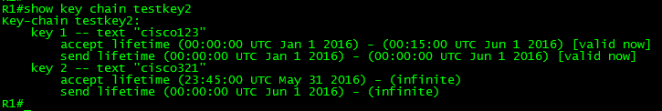
Key-chain configuration example with time-based key rotation:
!
key chain testkey2
key 1
key-string cisco123
cryptographic-algorithm hmac-sha-1
accept-lifetime 00:00:00 Jan 1 2016 00:15:00 Jun 1 2016
send-lifetime 00:00:00 Jan 1 2016 00:00:00 Jun 1 2016
key 2
key-string cisco321
cryptographic-algorithm hmac-sha-1
accept-lifetime 23:45:00 May 31 2016 infinite
send-lifetime 00:00:00 Jun 1 2016 infinite
end
!
In this example, the router will accept key 1 with password cisco123, until 12:15 AM on June 1, 2016. The router will send this same key until 12:00 AM on the same date (June 1, 2016). Also, the router will start accepting key 2 with password cisco321, at 11:45 PM on May 31, 2016. Worth to mention key chain rotation depends on accurate time and date on the devices.
To verify the key chain, use the show key chain {keychain-name} command.

Key Chain Association
This is the final step of the configuration. To associate the Key Chain to the interface, use the command ip ospf authentication key-chain {key chain-name}. Remember, a single key chain can be used for multiple interfaces.
!
interface Ethernet0/0
ip ospf authentication key-chain mykey
!
OSPF Enhanced Authentication configuration Example:
For this example I will use the following scenario:
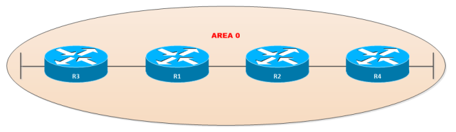
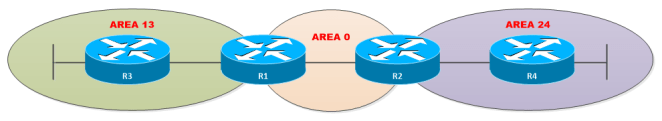
The network is currently doing authentication using MD5 Encryption (Type 2) between R1 and R3 and the authentication used for R1, R2 and R3 are Simple Passwords (Type-1).


A new change was requested by the Information Security team to increase the level of encryption along the network as follows:
- For the segment between R1, R2 and R4 use SHA-1 with password cisco421
- For the segment between R1 and R3 use SHA-256 with password cisco31
- The DUE date to complete the change is Jun 1, 2016
So let’s do it!
First let’s take a quick look only to the relevant configuration:
R1:
!
interface Loopback0
ip address 1.1.1.1 255.255.255.255
!
interface Ethernet0/0
ip address 192.168.124.1 255.255.255.0
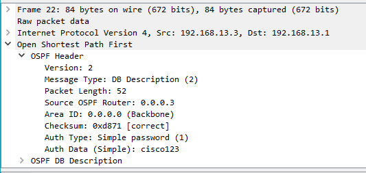
ip ospf authentication-key cisco124
!
interface Ethernet0/1
ip address 192.168.13.1 255.255.255.252
ip ospf authentication message-digest
ip ospf message-digest-key 1 md5 cisco13
ip ospf network point-to-point
!
router ospf 1
router-id 0.0.0.1
area 0 authentication
network 1.1.1.1 0.0.0.0 area 0
network 192.168.13.1 0.0.0.0 area 0
network 192.168.124.0 0.0.0.255 area 0
!
ntp master 1
!
R2:
!
interface Loopback0
ip address 2.2.2.2 255.255.255.255
!
interface Ethernet0/0
ip address 192.168.124.2 255.255.255.0
ip ospf authentication
ip ospf authentication-key cisco124
!
interface Ethernet0/1
ip address 172.16.20.2 255.255.255.0
!
router ospf 1
router-id 0.0.0.2
network 2.2.2.2 0.0.0.0 area 0
network 172.16.20.0 0.0.0.255 area 0
network 192.168.0.0 0.0.255.255 area 0
!
ntp server 192.168.124.1
!
R3:
!
interface Loopback0
ip address 3.3.3.3 255.255.255.255
!
interface Ethernet0/0
ip address 192.168.13.2 255.255.255.0
ip ospf authentication message-digest
ip ospf message-digest-key 1 md5 cisco13
ip ospf network point-to-point
!
interface Ethernet0/1
ip address 172.16.30.3 255.255.255.0
!
router ospf 1
router-id 0.0.0.3
network 3.3.3.3 0.0.0.0 area 0
network 172.16.30.0 0.0.0.255 area 0
network 192.168.13.2 0.0.0.0 area 0
!
ntp server 192.168.13.1
!
R4:
!
interface Loopback0
ip address 4.4.4.4 255.255.255.255
ip ospf 1 area 0
!
interface Ethernet0/0
ip address 192.168.124.4 255.255.255.0
ip ospf authentication
ip ospf authentication-key cisco124
ip ospf 1 area 0
!
interface Ethernet0/1
ip address 172.16.40.4 255.255.255.0
ip ospf 1 area 0
!
router ospf 1
router-id 0.0.0.4
!
ntp server 192.168.124.1
!
In the above output we can see that R1 has a simple password authentication configured directly to the area, while the crypto authentication is applied directly to the interface that connects to R3.
The other routers have configured the authentication parameters directly on the interface. Please also note R1 is acting as Clock Server for all routers in the network.
After checking the clock in all routers, we have determined that a possible solution is implementing extended authentication with rotary passwords for the segment between R3 and R1. Using this solution, we can switch the crypto algorithm without loose connectivity.
Unfortunately we cannot use the same solution for routers 1, 2 and 4. The reason is because Enhanced Authentication is intended only for Type-2 Authentications.
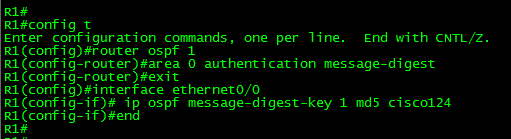
First let’s configure the key chain to be used for the link between R3 and R1 using rotary passwords.
!
key chain R3-TO-R1
key 1
key-string cisco13
cryptographic-algorithm md5
accept-lifetime 00:00:00 Jan 1 2016 00:15:00 Jun 1 2016
send-lifetime 00:00:00 Jan 1 2016 00:00:00 Jun 1 2016
key 2
key-string cisco31
cryptographic-algorithm hmac-sha-256
accept-lifetime 23:45:00 May 31 2016 infinite
send-lifetime 00:00:00 Jun 1 2016 infinite
end
!
The above key chain meets the requirements. It will maintain the connectivity using the current MD5 encryption algorithm until 15 minutes after midnight in June 1 (Key 1) and will also start accepting SHA-256 from May 31 at 23:45 hours (Key 2).
We can use the same key chain in both routers, R3 and R1. Lastly we have to assign the key chain to the interface connecting both routers.
R3:
!
interface Ethernet0/0
ip ospf authentication key-chain R3-TO-R1
!
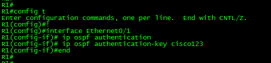
R1:
!
interface Ethernet0/1
ip ospf authentication key-chain R3-TO-R1
!
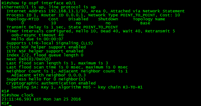
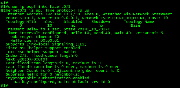
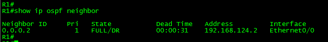
Now let’s verify the results of this configuration:


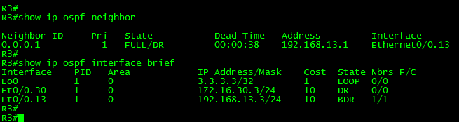
As can be seen in the above output, the current valid key is Key 1, with the current authentication. The interface output shows the key chain (R3-TO-R1) association.
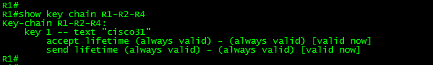
Now let’s configure the authentication settings for the segment between R1, R2 and R4.
!
key chain R1-R2-R4
key 1
key-string cisco421
cryptographic-algorithm hmac-sha-1
end
!
As can be seen in the above configuration, the key chain was created with key 1 for SHA-1 with the password cisco421. By default the key chain will set the “accept” and “send” lifetime as always valid if is not manually set.
All three, routers, R1, R2 and R3 are connected to the segment 192.168.124.0/24 using the interface Ethernet0/0. The final step would be applying the same key chain in all three routers and enable the key chain to the interface Ethernet0/0. Remember, in this case when moving from Type 1 to Enhanced Type 2 authentications, the change may be disruptive. You have 40 seconds (OSPF default dead timer) before the router declare its neighbors down.
So finally let’s associate the interface to the routers 1, 2 and 4:
!
interface Ethernet0/0
ip ospf authentication key-chain R1-R2-R4
!
Let’s take a look to the output of show ip ospf interface Ethernet0/0 and Ethernet 0/1 in R1:

R1 as shown above is now doing authentication SHA-1 in the interface Ethernet0/0 as requested. The interface Ethernet0/1 connecting with R3 is still doing Authentication MD5.
Finally let’s test the configuration with rotary authentication. For this purpose I’ll manually set the clock to 23:46:00 May 31 2016 and will check the interface status in R3 and R1.
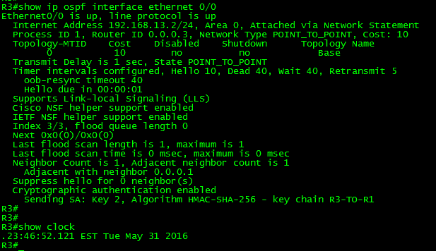

As can be seen in the above output, the interface Ethernet0/1 in R1 and the interface Ethernet0/0 in R3 have changed to Authentication HMAC-SHA-256. In this case the change was automatic due the automatic time-based key rotation feature.
It is time to close this post. Thank you for visiting.


 WARNING.!