In the last post (OSPF Passive Interface), I have mentioned that enabling routing everywhere may increase the chances of the insertion of unauthorized devices. What I mean by this is when we enable OSPF within the interface or using the network command in the OSPF process, we also allow automatic neighbor discovery and adjacency forming in certain network types such broadcast networks. Using passive-interface in OSPF we make sure no hello packets are sent in stub networks; thus, adjacencies won’t form in these network segments. But what about the routers placed in transit networks? How can we protect them without disabling the Hello packets?
Well, in this case, what we can do its force the routers to authenticate in order to establish the adjacencies.
OSPF Authentication Types:
Three types of authentications are currently supported by OSPF:
- Type 0 – Null – Is the default and means that there is no authentication and is typically used in links where authentication is not required.
- Type 1 – Simple Password – In this type of authentication, the passwords are exchanged in plaintext (very insecure).
- Type 2 – Cryptographic – In this type of authentication, the password is encrypted using MD5. (Now is possible the use of SHA encryption with OSPF in new IOS versions. This will be discussed in the following post)
OSPF Authentication Configuration:
OSPF authentication is a 2 step configuration; the first step is enabling the type of authentication to be used. It can be enabled at the Process level or at the Link level. By default, the link level authentication overrides the process level authentication.
To enable OSPF authentication at the process level, use the area {area-id} authentication command for Simple Password authentication; adding the keyword message-digest changes the authentication to Cryptographic type 2 (MD5).
To enable OSPF authentication at the interface level use the ip ospf authentication command for Simple Password authentication; adding the keyword message-digest changes the authentication to Cryptographic type 2 (MD5).
To configure OSPF null authentication to a link connecting to a neighbor, use the ip ospf authentication null command. As mentioned before, null authentication is typically used in links where other types of authentication are been used but is not required in a particular link. More details and examples in the next post.
The second step is to define the password to be used either plaintext or encrypted. The authentication passwords are always configured on the link.
To configure the authentication passwords in plaintext use the interface command ip ospf authentication-key {0|7} {password}.
The option 0 or 7 inside the curly brackets means the user is entering the password in plain text (option 0) while the option 7 means the user is entering an already encrypted Cisco proprietary Type-7 password. The option 0 is the default and is not required to be set.
To configure the authentication passwords as Type 2 (MD5) use the interface command ip ospf message-digest-key {key-number [1-255]} md5 {0|7} {password}.
Type 2 authentication supports up to 255 different keys. The key number and password must match between the routers. Using different keys allow for quick changes of passwords and to use multiple passwords per area.
OSPF Authentication Configuration for Virtual-Links:
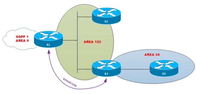
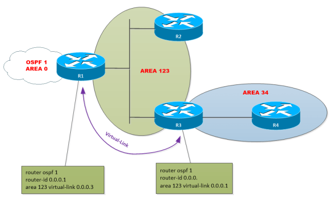
A Virtual Link is an OSPF tunnel, a multi-hop point-to-point unicast adjacency; it is, in essence, an extension of Area 0 across (transit area) another area. When configured a P2P logical interface is created with state P2P and attached to Area 0. The Virtual-Link configuration follows the same rules described before. Requires define the authentication Type which can be defined in the area or over the virtual-link definition and the password. Because the logical interface VL is created when the virtual link is defined in the process, it also has to be defined within the virtual link configuration in the process. Use the following combinations to configure the Virtual-Link Authentication:
Simple password configuration:
area {area-id} virtual-link {router-id} authentication authentication-key {password}
Cryptographic configuration:
area {area-id} virtual-link {router-id} authentication message-digest message-digest-key {key-number [1-255]} md5 {0|7} {password}.
OSPF Authentication Configuration Examples:
For this set of examples, we will use the topology we have been using so far.


Initial Configurations:
R1:
!
interface Loopback0
ip address 1.1.1.1 255.255.255.255
!
interface Ethernet0/0
ip address 192.168.124.1 255.255.255.0
!
interface Ethernet0/1
ip address 192.168.13.1 255.255.255.0
!
router ospf 1
router-id 0.0.0.1
network 1.1.1.1 0.0.0.0 area 0
network 192.168.0.0 0.0.255.255 area 0
passive-interface default
no passive-interface Ethernet0/0
no passive-interface Ethernet0/1
!
R2:
!
interface Loopback0
ip address 2.2.2.2 255.255.255.255
!
interface Ethernet0/0
ip address 192.168.124.2 255.255.255.0
!
interface Ethernet0/1
ip address 172.16.20.2 255.255.255.0
!
router ospf 1
router-id 0.0.0.2
network 2.2.2.2 0.0.0.0 area 0
network 172.16.20.0 0.0.0.255 area 0
network 192.168.0.0 0.0.255.255 area 0
passive-interface default
no passive-interface Ethernet0/0
!
R3:
!
interface Loopback0
ip address 3.3.3.3 255.255.255.255
!
interface Ethernet0/0
ip address 192.168.13.3 255.255.255.0
!
interface Ethernet0/1
ip address 172.16.30.3 255.255.255.0
!
router ospf 1
network 3.3.3.3 0.0.0.0 area 0
network 172.16.30.0 0.0.0.255 area 0
network 192.168.13.0 0.0.0.255 area 0
passive-interface default
no passive-interface Ethernet0/0
!
R4:
!
interface Loopback0
ip address 4.4.4.4 255.255.255.255
ip ospf 1 area 0
!
interface Ethernet0/0
ip address 192.168.124.4 255.255.255.0
ip ospf 1 area 0
!
interface Ethernet0/1
ip address 172.16.40.4 255.255.255.0
ip ospf 1 area 0
!
router ospf 1
router-id 0.0.0.4
passive-interface default
no passive-interface Ethernet0/0
!
The Switch interfaces where the routers are connected were configured as follows:
!
interface FastEthernet0/[1-4]
switchport trunk encapsulation dot1q
switchport mode trunk
!
Task 1:
Let’s start applying Simple Password Authentication (Type-2) to the segment between R1 and R3 with the password cisco123. R1 must use interface level authentication and R3 must use Area authentication.
R1:
R3:

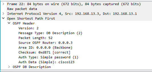
An interesting thing to mention is that all OSPF packets are authenticated.
Let’s take a look to the different OSPF packets:
Hello Packet Header:

Link-State Database Description (LSDB) Header:
Link-State Request:

Link-State Update:

Link-State Acknowledge:

As you can see in the above examples, the Authentication Type is Simple password (1) and the password (cisco123) is shown in plain text format.
OSPF authentication doesn’t mean Encryption, meaning that the content of the packet is perfectly readable. The objective of OSPF Authentication is only to protect the Router control plain avoiding the insertion of unauthorized routes injected by unauthorized devices.
Task 2:
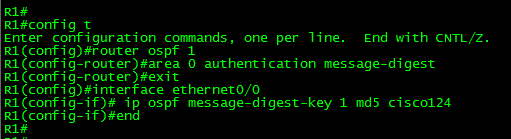
For this task, let’s apply Cryptographic Password Authentication (Type 2) to the network segment between R1, R2, and R4 with the password cisco124. R1 must use Area authentication while R2 and R4 must use interface level authentication.
R1:
R2:

R4:

Let’s take a look at the Hello packet of R1 in the interface E0/0:

As you can see in the output the Authentication Type now is Cryptographic (2). You will also find the Key ID used to authenticate, the sequence number and the encrypted password contained in the Auth Crypt Data field. Using sequence numbers prevents replay attacks where the OSPF packets are captured, modified and retransmitted to the router.
In this case, we use the same password because is a shared segment, however in other network types such point-to-point, different passwords can be used.
OSPF Authentication Verification and Troubleshooting:
In order to verify the authentication use the show ip ospf interface {interface-id} command.

The above output displays the type of authentication used and the key id used to authenticate in the interface Ethernet0/0 for the segment 192.168.124.0/24 where R1, R2, and R4 reside. Then the same output displays the type of authentication used, in this case, Simple password for the segment 192.168.13.0/24 where R1 and R3 connects.
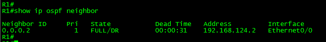
Another way to verify if the authentication succeeds is by checking the neighbor table using the show ip ospf neighbor command. When the authentication fails, it will remove the neighbor from the table.
In order to demonstrate the troubleshooting process, I’ve made the some changes (misconfigurations I would say) to the routers previously configured.
The problem:
After OSPF Authentication was configured in the routers, the connectivity to the segments 172.16.30.0/24 and 172.16.40.0/24 has been lost.

After confirming the adjacencies to R3 and R4 were lost, we can troubleshoot the adjacencies using the debug ip ospf adj command. To turn off the debug use the command: undebug all.

Aha! Seem that we have found the problems. The debug output showed above give us details about the issue:
The first problem found: The router has received in the interface Ethernet0/1 a packet with mismatched Authentication Type. The received packet is using Simple Password Authentication (Type 1), but the local router is using Cryptographic Authentication (Type 3).


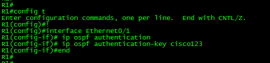
This was an easy catch; the solution will be enabling Simple Password (Type 1) authentication in the interface Ethernet0/1 of R1.
R1#config t
Enter configuration commands, one per line. End with CNTL/Z.
R1(config)#interface e0/1
R1(config-if)#ip ospf authentication
R1(config-if)#ip ospf authentication-key cisco123
R1(config-if)#no ip ospf message-digest-key 1 md5 cisco123
R1(config-if)#end
R1#
The other problem: The router has received in the interface Ethernet0/0 a packet with Mismatched Authentication Key – ID 1. This debug message is self-explanatory. The password received in the interface doesn’t match with the local one.
Let’s compare the configurations:


Wait a minute! At first sight, the passwords look identical. But are they actually identical?
Well, in this problem I have introduced a common problem when configuring passwords. I have added a blank space at the end of the password in R4. Blank spaces also count as part of passwords.

The solution in this case is remove the MD5 key 1 and re-enter it. You can also copy the line from R1 or R2 and paste it into the interface Ethernet0/0 configuration.
It is time to close this post.
Thank you for visiting.