OSPF Filtering with Summarization

In today’s post, we will continue discovering the different ways we can perform filtering in OSPF.

Previously we depict two common ways to filter routes in OSPF, the first one using LSA Type-3 filtering and the second was filtering NSSA external routes directly to the redistribution process in OSPF.   Worth mentioning that for the second example in the previous post (Goal 2) I did a change in the original configuration.   This was done just to illustrate a way to instruct OSPF to not to impose the P-bit into the redistributed routes.   However this effect could be achieved by doing a simpler change which will help us to introduce the third OSPF filtering type:

Filtering with Summarization

This type of filtering as its name implies works in conjunction with OSPF Summarization.  The idea behind this type of filtering is done by grouping a set of prefixes by using summarization and then suppress the newly generated LSA propagation adding the not-advertise keyword.

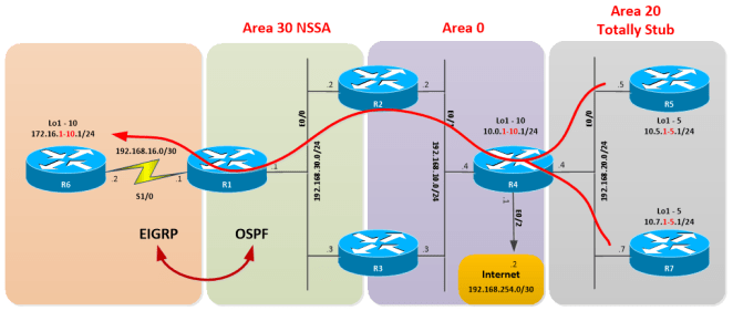
Let’s use the previous network topology for the examples.   (Please note the addition of Loopbacks 16 to 18 in R6).

OSPF-FILTERING-2-01

Here you can download the diagram and configuration files: OSPF-Filtering – Part II

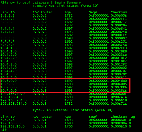
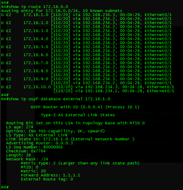
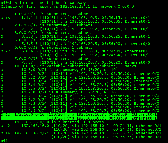
Let’s take a look to the routing table from the perspective of R4, but let’s focus on the routes coming from the EIGRP domain:

OSPF-FILTERING-2-02

Ok, so far we know the prefixes 172.16.1.0/24 to 172.16.10.0/24 and 172.16.16.0/24 to 172.16.18.0/24 are being redistributed from R6 (EIGRP domain) into OSPF in R1 and then Summarized into a single /16 supernet.  This redistribution makes R1 an ASBR.  We also know R1 is placed into an NSSA area.   This means the routes were originally advertised as Type-7 LSAs by R1 and then translated into Type-5 LSAs by one of the ABRs connecting the NSSA and flooded into Area 0 and from there to the rest of the OSPF domain.

Having this information on hand, let’s play a little bit with Filtering with summarization.

Goal 1:

Summarize the routes coming from the EIGRP domain into two /20 supernets (172.16.0.0/20 and 172.16.16.0/20).  Apply filtering in such way that the network 172.16.0.0/20 only be accessible from R1, the second segment can be reached from anywhere in the network.

Ok, the task is very straightforward.  What we should do is remove the previous summarization and generate two summary routes; however one of the summary routes should not be advertised.  This can be achieved by adding the not-advertise keyword to the summary route at which we want to apply the filter.    Now, I would like to demonstrate the effect in the LSDB of adding the keyword after the summary route was created.   So, let’s do it.

In R1 (ASBR):

!
router ospf 1
no summary-address 172.16.0.0 255.255.0.0
summary-address 172.16.0.0 255.255.240.0
summary-address 172.16.16.0 255.255.240.0
exit
!

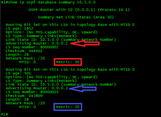
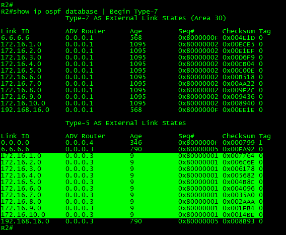
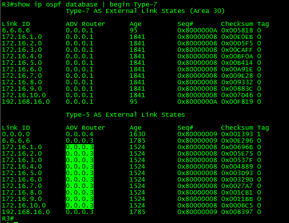
Let’s take a look at the Link-State Database (LSDB) in R1, specifically the Type-7 AS External LSAs:

OSPF-FILTERING-2-03

As can be seen in the above output, now we have two summary Type-7 LSAs.   Also, note the LSAs have the P-Bit set (In blue).   This will trigger the translation between Type-7 into Type-5 LSAs in the ABR.   Both summary routes will be advertised to the OSPF domain.

The last part of the goal requires filtering the first range.   So, to apply the filter, just add the not-advertise keyword to the desired summary-address command.

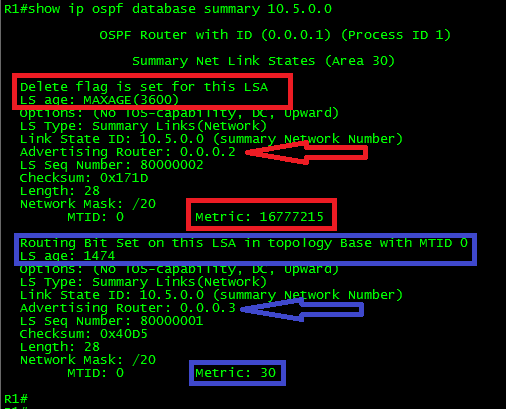
Before adding the filter let’s debug the ospf lsa-generation and observe the changes:

OSPF-FILTERING-2-04

I never get tired of repeating that the use of any debug must be done with extreme caution.

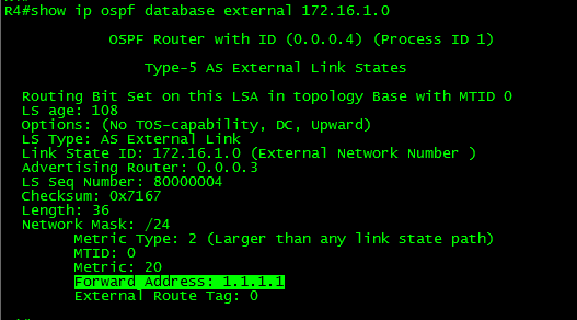
As can be seen in the above output, after the changes were applied R1 generated an external LSA for the network 172.16.0.0/20 with LS age set to 3600 seconds which is the max age.  The LSA metric was set to 16777215 or (max-metric for routes in the OSPF database) LSInfinity.  When the max age timer on an LSA reaches 60 minutes, the LSA is discarded.    The result is: Yes, the filtering of the summary network 172.16.0.0/20.

OSPF-FILTERING-2-05

As seen in the above output, the filter worked as expected.   This solution is suitable for this particular situation, where only the network in R1 needs the access.   They will use the EIGRP routes for this purpose.

OSPF-FILTERING-2-06

However, these routes will not be reachable from anywhere else in the OSPF domain as can be seen next.

OSPF-FILTERING-2-07

As can be seen in the above output, the networks are reachable from the desired points of the network, the traffic flows accordingly; the network is stable, and the goal was achieved.

After a few days, we have received the following information:

“Within the following weeks, some new network segments will be created in R2 and R3 for Servers connected to Area 30.   This change will require allowing access to the network 172.16.0.0/20 in the EIGRP domain from Area 30.”

OSPF-FILTERING-2-08

In this case, the filtering solution provided before will not work.  To achieve this will be required to allow the advertisement of the summary networks to R2 and R3 respectively and stop the advertisement there.

This requirement is similar to Goal 2 of the previous post.  So, let’s do it.

Goal 2

Apply OSPF filtering to the summary route 172.16.0.0/20 in such way this network only be accessible from AREA 30.  The second segment can be reached from anywhere in the network.

Let’s recap a bit what we did to solve it in the last post.   What it was done was removing the summarization of the route in question, and then apply filtering directly into the redistribution process using the keyword NSSA-only.

In this case, the given solution in the previous post won’t work.  This is because we have two summary routes from which only one has to be filtered.

Luckily OSPF provides the same functionality when summarizing external routes in Not-so-Stubby-Areas, meaning that we can use the keyword NSSA-only, and at the same time suppress the P-bit from being imposed.    The direct result will be the no translation from Type-7 to Type-5 LSAs in the ABR, thus, the desired summary route won’t be advertised beyond Area 30.

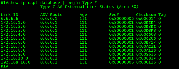
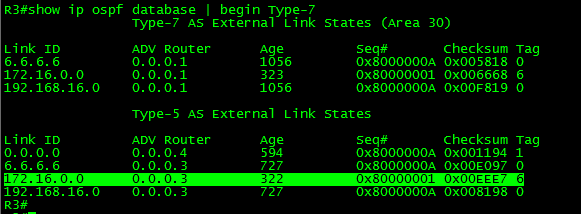
Let’s make the change and take a look to the external type-7 LSAs in R1:

In R1 (ASBR):

!
router ospf 1
no summary-address 172.16.0.0 255.255.240.0 not-advertise
summary-address 172.16.0.0 255.255.240.0 nssa-only
exit
!

OSPF-FILTERING-2-09

As can be seen in the above output, now R1 has generated Type-7 LSAs for both summary routes.   But if you look (in blue) the options field for each one, the first LSA has the Type7/5 bit imposed while the other says No Type 7/6 translation.    In other words, only the LSA with the P-bit set will be translated to Type-5 LSA in the ABR and flooded into Area 0.

Let’s take a look from the perspective of R2:

OSPF-FILTERING-2-10

As shown in the above output, in R2 we can find Type-7 LSAs for both prefixes but note (in blue) there is only one Type-5 LSA.   This confirms the change.   Only the LSA corresponding to the prefix 172.16.16.0/20 was translated into Type-5.    For brevity, I’m showing only R2, but it is the same output from both ABRs.  (If you look closer to the Type-5 LSAs, the advertising router is R3.   This is because the Type-7/5 translator is R3.  Thus, R3 was the one advertising the generated Type-5 LSAs to R2.)

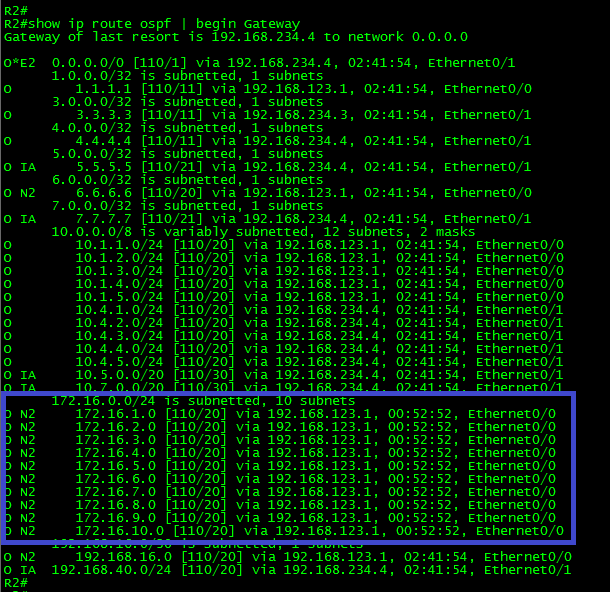
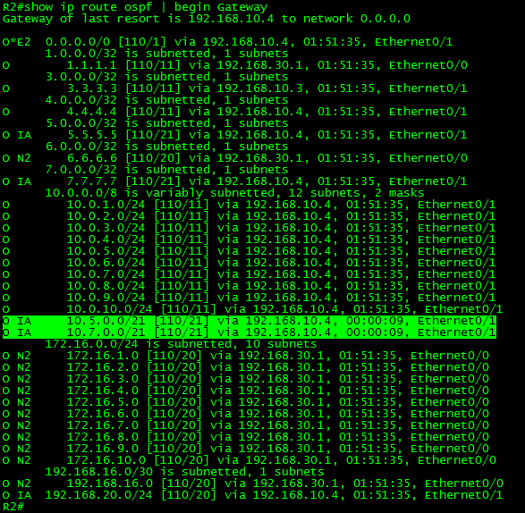
Now, from R2 and R3 we can find both routes as “O N2” or OSPF NSSA external type 2 routes, meaning that both summary routes can be reached from Area 30 as shown in the next output:

OSPF-FILTERING-2-11

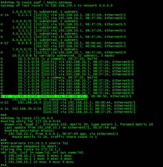
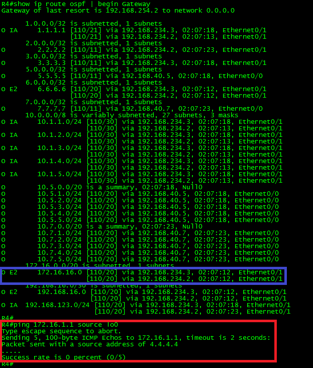
Finally, let’s check the changes from R4’s perspective:

OSPF-FILTERING-2-12

As can be seen, the goal was achieved, only the subnet 172.16.16.0/20 from the EIGRP is reachable from there.   What about the routers in Area 40?  They don’t have individual routes for external networks.   Stub areas generate the default route in OSPF by default, being the ABR the next-hop to reach external networks, thus they rely on R4 to route the traffic.  Therefore, they won’t be able to reach the filtered routes either.

After a few weeks a new request is received:

“The traffic from Area 30 and the EIGRP domain to the segments 10.4.1.0/24 to 10.4.3.0/24 must be filtered.”

Ok, let’s get started.

Goal 3

Apply OSPF filtering in such way that eastbound traffic from R1 towards 10.4.1.0/24 to 10.4.3.0/24 be unreachable; all other networks must work as usual.

Let’s start looking at the traffic path from R1’s perspective:

OSPF-FILTERING-2-13

As can be seen in the above output, the desired traffic is been load-balanced via R2 and R3.

We know that R2 and R3 are ABRs, and we also know that we can summarize the desired networks into 10.4.0.0/22.   Then OSPF filtering with summarization can be a suitable solution.

So in order to achieve the goal, we have to apply the filter into both ABRs.   If we apply it to only one of them, the result will be…  Yes, you got it, some sort of Traffic Engineering.

OSPF-FILTERING-2-14

So let’s start by applying the filter into the first ABR.

Remember, to filter the summary route, just add the not-advertise keyword to the summarization command.   Also remember, when doing summarization, in ABRs the command area {area-source} range {network-id} {subnet-mask} OSPF process command is used; where {area-source} as its name implies, is from which area is the router receiving the desired LSAs.

In R2 (ABR):

!
router ospf 1
area 0 range 10.4.0.0 255.255.252.0 not-advertise
exit
!

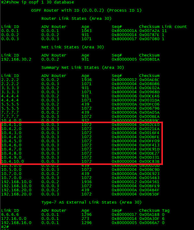
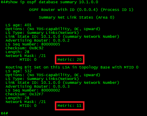
With this change applied only in R2, the summary route 10.4.0.0/21 won’t be advertised to R1, but the individual routes will by reachable via R3 as shown below:  (Traffic Engineering effect.)

OSPF-FILTERING-2-15

Finally, the only missing part of achieving the goal is applying the same filter into R3 ABR.

In R3 (ABR):

!
router ospf 1
area 0 range 10.4.0.0 255.255.252.0 not-advertise
exit
!

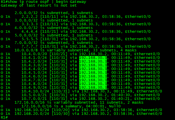
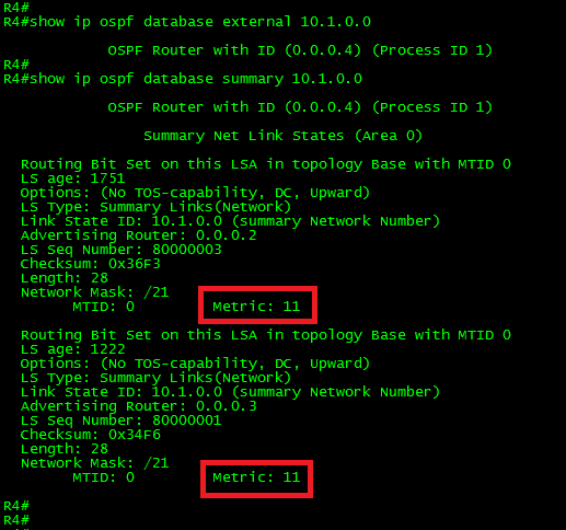
Let’s take a look now to the routing table in R1 and R6 (EIGRP domain):

OSPF-FILTERING-2-16

OSPF-FILTERING-2-17

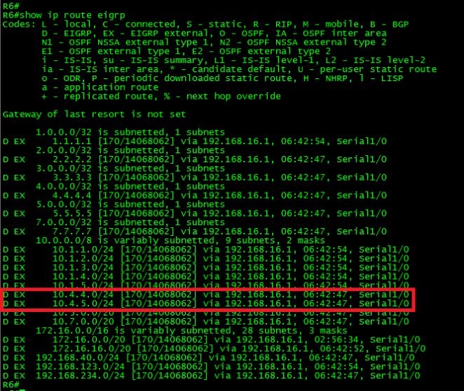
As can be seen, now only the routes to 10.4.4.0/24 and 10.4.5.0/24 from R4 are present in the routing tables of R1 and R6.

Let me explain why:

When we apply the command area 0 range 10.4.0.0 255.255.252.0 not-advertise on both ABRs, they have generated and flooded a Type-3 LSA corresponding to the summary address with the LS age set to its max value (3600 seconds) and the metric set LSInfinity.  Therefore, these LSAs were discarded within Area 30.   Subsequently, the routes were no longer redistributed into the EIGRP domain.

It is time to close this long post.  In the next one, we will continue discussing OSPF Filtering but this time using Distribute-Lists.

Thank you for visiting.

OSPF Filtering (LSA Type-3 & NSSA External)

In today’s post, we will talk about the different ways we can perform filtering in OSPF.

OSPF is a Link-State protocol; hence, we can foresee that filtering is a little more difficult to perform than with any other IGP.   The reason is that link-state protocols do not advertise routes per se, they advertise topology information.   We have to keep in mind that routers in the same area have or share an identical copy of the Link-State Database (LSDB) for that particular area, this implies that OSPF filtering can only be applied at certain points of the network, being these the ABRs or ASBRs.

OSPF route filtering types:

In Cisco OSPF implementation there are three major types of OSPF filtering:

  • LSA Type-3 Filtering: This type of filtering prevents the ABR from creating particular Type-3 summary LSAs.
  • NSSA External Routes Filtering: This type of filtering prevents the P-bit (Propagate Bit) being imposed to the Type-7 LSAs, thus the Type-7 to Type-5 translation does not take place in the ABR.
  • Filtering with Summarization: This type of filtering work in conjunction with OSPF summarization, adding the not-advertise keyword.

Now, there are some cases when we can apply filtering to the router’s routing table itself, preventing routes learned from the OSPF RIB to be installed into the global RIB.  This scenario, in particular, may result into traffic blackholing because it doesn’t filter the LSA, only the route.

The OSPF RIB filtering can be applied anywhere.

LSA Type-3 Filtering

This type of filtering allows ABRs to filter Type-3 LSAs.   Remember, the ABRs do not forward Type-1 or Type-2 LSAs; instead, they create Type-3 LSAs with the values corresponding to the subnets and the cost from the ABR to these subnets.  This feature filter the type-3 LSA before is injected into another area.  Thus, the requirement of identical LSDB within the area is still met.

To configure LSA Type-3 filtering, use the area {area-source} filter-list prefix {prefix-list-name} in|out OSPF process command.   Worth mentioning that when filtering routes into the backbone area (Area 0) will filter the advertisement within all areas in the routing domain while filtering into a non-backbone area will filter the advertisement of routes only within the targeted area.

Let’s use the same topology we have been using so far but with a few changes for the examples:

OSPF-FILTERING-01

Here you can download the diagram and configuration files: OSPF-Filtering – Part I

Among the changes done with respect to the topology used in the previous post, I can mention the advertisement of networks in R1, R4, R5 and R7 using sub-interfaces instead loopbacks, all routers have loopback0 configured (Not shown in the diagram). Another change is the renumbering of the transit networks and the renumbering of Area 20 to Area 40 only as Stub.

Let’s take a look to the routing table from the perspective of R1:

OSPF-FILTERING-02

As can be seen in the above output, R1 is routing the eastbound traffic towards the networks in R5 and R7 through R2 and R3 (load-balancing).    The routes are being advertised as “O IA” or OSPF inter-area, meaning advertised from the ABRs as Type-3 LSAs.

OSPF-FILTERING-03

Let’s apply LSA Type-3 filtering to these routes.

Goal 1:

Eastbound traffic from R1 destined to the networks 10.5.0.0/20 in R5 must be advertised only from R3 and the networks 10.7.0.0/20 in R7 must be only advertised only from R2.

OSPF-FILTERING-04

To have a clear vision of how it works, I will describe the advertisement process.

The source of the routes to be filtered passes from Area 40 through R4 (ABR) which has OSPF summarization configured.  R4 which has the interface E0/0 into Area 40 summarize the Type-1 LSAs received from R5 and R7 and generate two Type-3 summary LSA for the summary routes (10.5.0.0/20 and 10.7.0.0/20), R4 set itself as the advertising router for the summary LSAs in Area Zero (Backbone Area) and set the cost to reach the networks. Then this Type-3 LSAs are flooded within the area.

Next, R2 and R3 which are also ABRs generates and flood their own Type-3 LSAs for Area 30, setting themselves as the advertising router for both summary routes and adding the cost advertised from R4 to the cost from each ABR to R4.

From the perspective of R1, the Type-3 LSAs were advertised from R2 and R3 respectively and the AREA SOURCE of the advertisements is Area 0.      This means the prefix-list to be used to filter the LSAs must go out of area zero (outbound).

So, for the first part: Traffic destined to 10.5.0.0/20 through R3, let’s apply filtering in R2 denying the summary 10.5.0.0/20 in the outbound direction from Area 0.

Let’s take a look to the Summary LSAs of 10.5.0.0/20 from R1’s perspective before applying the change:

OSPF-FILTERING-05

As can be seen in the above output, we have two summary LSAs in R1 (Area 30) corresponding to the summary network 10.5.0.0/20, one LSA advertising the network from R2 (ABR), and the other from R3 (ABR) with identical cost (metric),  thus the network is load-balanced between both ABRs.   We had already established this; you may wonder why are we seeing this again?

The answer is:   To show you the effect of apply Type-3 LSA filtering in the LSDB.

Ok, let’s apply the following change in R2:

In R2 (ABR):

!
ip prefix-list Filter-Net-10-5 seq  5 deny 10.5.0.0/20
ip prefix-list Filter-Net-10-5 seq 10 permit 0.0.0.0/0 le 32
!
router ospf 1
area 0 filter-list prefix Filter-Net-10-5 out
exit
!

Let me explain the filter:

  1. The prefix-list Filter-Net-10-5 sequence 5 will deny the specific subnet 10.5.0.0/20
  2. The prefix-list Filter-Net-10-5 sequence 10 will permit any other subnet. The syntax 0.0.0.0/0 matches any network and the le (less-or-equal) set the range of subnets lower or equal to /32.   This is the equivalent to permit any.    It is important to remember at the end of prefix-lists, access-lists or even route-maps there is an implicit deny.   Therefore without this particular entry, all subnets will be denied by default.
  3. The OSPF process command area 0 filter-list prefix Filter-Net-10-5 out, set the filter for traffic sourced from Area 0 which match the prefix-list Filter-Net-10-5 in the outbound direction.

Let’s take a look to the Summary LSAs of 10.5.0.0/20 in R1 after we applied the change:

OSPF-FILTERING-06

As can be seen in the above output, now the LSA advertised from R2 (ABR) has the delete flag set.   The LS age was changed in R2 to 3600 seconds which is the max age and the metric also was set to the max-metric for routes in the OSPF in decimal.  This is also known as LSInfinity.  Remember: When the max age timer on an LSA reaches 60 minutes, the LSA will be discarded.

Let’s take a look to the routing table in R1:

OSPF-FILTERING-07

As can be seen in the output, now eastbound traffic towards R5 is following the desired path.  We still have pending the rest of the goal.    To force the traffic from R1 to R7 through R2, we have to make basically the same change, but in R3 (ABR).

So, let’s do it.

In R3 (ABR):

!
ip prefix-list Filter-Net-10-7 seq  5 deny 10.7.0.0/20
ip prefix-list Filter-Net-10-7 seq 10 permit 0.0.0.0/0 le 32
!
router ospf 1
area 0 filter-list prefix Filter-Net-10-7 out
exit
!

Again, let’s take a look to the routing table in R1:

OSPF-FILTERING-08

Ok, as can be seen in the above output, now the eastbound traffic towards R7 is following the desired path.   With this last change, the goal 1 was achieved.

Let’s move on to the next type of filtering.

NSSA External Route Filtering

This type of filtering is applied in ASBRs.   What it does is preventing the P-bit or Propagate-Bit being imposed to the Type-7 LSAs.    Let’s recall a little bit.    NSSA generate Type-7 LSAs to advertise external routes to the ABR.  The ABR then translate the Type-7 LSAs into Type-5 LSAs.    For the translation takes place, the ABR check every Type-7 LSA looking for the P-bit (Propagate-Bit), which is imposed by default in NSSA when redistributing in ASBRs.    Now, if the P-bit is not set, then the translation does not take place.    Remember, the flooding scope of Type-7 LSAs is NSSA areas only.

We can apply this filter to the redistribution itself with the keyword nssa-only at the redistribution OSPF process command.

I will not explain mutual redistribution in this post; however I want to show you the effect on the LSDB when applying the filtering into the redistribution in OSPF.

Let’s apply NSSA external route filtering to the routes coming from the EIGRP domain.

Goal 2:

Filter the routes coming from the EIGRP domain in such way the routes will only be accessible from Area 30.

To achieve this goal, first, I would make a small change required for this requirement.   I will remove the summarization in R1.    The reason to do this is because when using summarization in conjunction with filtering applied to the redistribution process, the summarization will override the P-bit suppression.   The summarized Type-7 LSA will be generated by the ASBR with the P-bit set.

So, let’s remove the summarization and check the NSSA external database in R1.

In R1 (ASBR):

!
router ospf 1
no summary-address 172.16.0.0 255.255.0.0
!

OSPF-FILTERING-09

OSPF-FILTERING-10

As can be seen in the above outputs, now the LSDB has individual Type-7 LSAs per network redistributed from the EIGRP domain with the P-bit set.   The direct result of this change is that the elected Type-5/Type-7 translator (R3 ABR in this case) will generate Type-5 LSAs for each Type-7 LSA advertised by R1 and will flood them to the Backbone area, and from there to the other areas as shown in the next output from R4.   This is an expected behavior.

OSPF-FILTERING-11

Now, let’s apply the NSSA external filtering adding the keyword nssa-only at the redistribution OSPF process command and observe the changes in the LSAs.

In R1 (ASBR):

!
router ospf 1
redistribute eigrp 100 subnets nssa-only
!

OSPF-FILTERING-12

As can be seen in the above output, now the LSAs were generated without the P-bit.    This will prevent the translation from Type-7 to Type-5 LSAs in the ABR.   The direct result will be that the EIGRP domain will be reachable only from Area 30.

Let’s take a look to the routing table in R4 for example.

OSPF-FILTERING-13

As can be seen, the routes for the EIGRP domain are not present therefore they are unreachable.

What about from routers in Area 30?   Let’s take a look to the routing table in R2 for example:

OSPF-FILTERING-14

The routes are there.     In the case of R2 and R3, they are ABRs; therefore, they have an interface connecting to the NSSA area.   Both ABRs have an LSDB for Area 0 and Area 30 respectively.  Note the routes are represented as “O N2” or OSPF NSSA external routes (Type-7 LSAs) instead “O E2” or OSPF external routes (Type-5 LSAs).   This means that if we had more routers only in Area 30, they will have reachability to the EIGRP domain via OSPF as “O N2” OSPF NSSA external routes.

It is time to close this long post.  In the next one, we will continue discussing OSPF filtering with summarization and other filtering options out there.

Thank you for visiting.

Traffic Engineering with OSPF Summarization (Part 2)

In the last post, we discussed how to modify the traffic path using summarization for external routes. Today we will continue discussing Traffic Engineering using OSPF summarization for intra-area routes.    So, let’s get started.

Just to recap:   The Inter-Area summarization is performed in ABRs, it summarizes Type-1 into Type-3 LSAs.   We can perform OSPF traffic engineering with summarization when we have multiple exit points out of an area or multiple exit points out of the autonomous system using longer prefix match over shorter prefix match routing.

Let’s use the same topology we have been using so far but with a few changes:

OSPF-SUMMARY-APPS-2-01

Here you can download the diagram and configuration files: TE with OSPF Summarization – Part II

Among the changes done with respect to the topology used in the previous post, I can mention the creation and advertisement of 10 loopback interfaces in R1, the interface Lo0 in R1 is not being advertised into OSPF and the re-numbering of the loopback interfaces in R4.  Another change is the ospf cost manually set to 20 in the Ethernet0/1 interface of R3.

Let’s take a look to the routing table from the perspective of R1:

OSPF-SUMMARY-APPS-2-02

As can be seen in the above output, R1 is routing the eastbound traffic through R2. This is because of the higher OSPF cost assigned in the interface Ethernet0/1 of R3.

Now let’s take a look to the routing table from the perspective of R4:

OSPF-SUMMARY-APPS-2-03

From R4’s perspective, westbound traffic is load-balanced.  So, let’s play a little bit with traffic engineering.

Goal 1:

Eastbound traffic from R1 destined to the loopback interfaces in R4 must go through R2.

Let’s start by taking a look to the LSA corresponding to the loopbacks:  (One loopback will be fine, the rest will have the same output.)

OSPF-SUMMARY-APPS-2-04

As shown in the output, both ABRs generated LSAs corresponding to the route 10.4.1.0/24; however only the route with best metric was installed in the routing table.

To achieve the goal, we will have to summarize the loopbacks in one of the ABRs and take advantage of longer prefix match over shorter prefix match routing.   Because the goal dictates route through R3 we have to summarize the routes in the ABR R2, so let’s summarize the loopbacks into a /20 range which covers from 10.4.1.1 to 10.4.15.254.

In R2 (ABR):

!
router ospf 1
area 0 range 10.4.0.0 255.255.240.0
!

Now let’s take a look to the routing table in R1:

OSPF-SUMMARY-APPS-2-05

As can be seen in the above output, a summary route (10.4.0.0/20) was advertised from R2 and the more specific routes are now being advertised by R3.

Let’s take a look at link-state database in R2, specifically Area 30:

OSPF-SUMMARY-APPS-2-06


What happened here was that unlike R3, R2 ABR instead generating Type-3 LSAs for each loopback interface, it generates a single Type-3 summary LSA.  Thus, R3 advertise more specific routes to R1.

Finally, let’s test the solution tracing routes to the loopbacks and directions in R5 and R7.

OSPF-SUMMARY-APPS-2-07

As seen in the above output, the solution worked.   The first trace sourced from Loopback1 in R1 route through R3 to reach Loopback1 in R4.  The other traces route through R2 to reach the loopbacks in R5 and R7 respectively.

Let’s complicate a little bit more the traffic engineering examples.

Goal 2:

We have been requested to divide the westbound traffic from R1 towards R4 loopback interfaces into two summary addresses and route them as follows:

  • The Summary Address 10.1.0.0/21 must be routed through R3.
  • The Summary Address 10.1.8.0/21 must be routed through R2.
  • In the routing table of R4, only the summarized ranges belonging to the loopback interfaces of R1 must be displayed.

So, let’s do it.

First, let’s take a look to the routing table from the perspective of R4:

OSPF-SUMMARY-APPS-2-08

As shown above, all of the westbound traffic is being load-balanced between R2 and R3 ABRs.

So, let’s proceed with the tasks:

Create the summary address 10.1.0.0/21 in R2 and the summary address 10.1.8.0/21 in R3.

In R2 (ABR):

!
router ospf 1
area 30 range 10.1.0.0 255.255.248.0
!

In R3 (ABR):

!
router ospf 1
area 30 range 10.1.8.0 255.255.248.0
!

Now let’s take a look to the routing table of R4:

OSPF-SUMMARY-APPS-2-09

Well, the summarization works as shown above.  The traffic towards R1’s loopback interfaces is routed as requested. But the routing table also has more specific routes instead summaries.   Also, note the routes for the external domain.   The routes to 172.16.0.0/16 and 192.168.16.0/30 are now been advertised only via R3.  But why?

Now we have two things to figure it out.

Let’s start with the summarization problem, and then we will see what happened to those routes.

For the summarization, we know that the more specific routes rule is working.  Now we have to find the way to suppress them.

If we also apply summarization of the specific routes in each ABR we will have again load-balancing.   Let’s make the change and take a look.   Of course, we have to apply the same summarization applied to the ABRs in an inverse way.   In other words, the summarization applied to R3 into R2 and vice versa.

In R2 (ABR):

!
router ospf 1
area 30 range 10.1.8.0 255.255.248.0
!

In R3 (ABR):

!
router ospf 1
area 30 range 10.1.0.0 255.255.248.0
!

After the changes were applied both ABRs will have summarization applied for both ranges in their routing process as follows:

OSPF-SUMMARY-APPS-2-10

OSPF-SUMMARY-APPS-2-11

Now, let’s take a look again to the routing table in R4:

OSPF-SUMMARY-APPS-2-12

Ok, the summary addresses are now being load-balanced, but wait a minute!  Now we have again the routes to the External domain load-balanced.  This means the change we just did is directly related.   We will go back to this in a minute.   Let’s finish the first problem.

As can be seen in the above output, the summary addresses are being load balanced because they have identical metric.

OSPF-SUMMARY-APPS-2-13

Now what we can do to change the traffic pattern is modify the metric to the summary addresses.

To do this, we will have to manually alter the cost on each ABR for the desired routes.

Let’s make the following change:

Because the summary Address 10.1.0.0/21 must be routed through R3, let’s modify the cost of the summary address in the ABR R2 and make it higher and let’s take a look at the result in the routing table of R4.

In R2 (ABR):

!
router ospf 1
area 30 range 10.1.0.0 255.255.248.0 cost 20
!

OSPF-SUMMARY-APPS-2-14

As shown in the above output, now the route 10.1.0.0/21 is now reachable only via R3.

Now, let’s take a look at the summary Type-3 LSA:

OSPF-SUMMARY-APPS-2-15

As can be seen, the metric of the LSA advertisement is now 20 when received from R2 and 11 when received from R3.   Now, the lowest metric wins thus its installed in the RIB.

Now let’s do the change for the other summary route.

Because the summary Address 10.1.8.0/21 must be routed through R2, let’s modify the cost of the summary address in the ABR R3 and make it higher and let’s take a look at the result in the routing table of R4.

In R3 (ABR):

!
router ospf 1
area 30 range 10.1.8.0 255.255.248.0 cost 20
!

OSPF-SUMMARY-APPS-2-16

As shown in the above output, now the route 10.1.8.0/21 is now reachable only via R2.

Finally, the desired traffic pattern was achieved and the task was completed.

Now, let’s talk about the External routes.  Why did they change when we applied the summarization?   This behavior is clearly defined in the RFC 3101, in section 2.3.   I would recommend you to read it.

Long story short:   It has to be with the forwarding address, or better said:  The way NSSA treat forward addresses when redistributing.   The selection process to choose the forwarding address is:  Choose the highest IP address of an internal address; if an internal address is not available, it will prefer the higher found OSPF stub network.

Let’s take a look to the external LSA:

OSPF-SUMMARY-APPS-2-17

In this case, the router has compared Loopback0 and Loopback1.  Because Loopback1 has the higher IP address it wins.

The Forward Address (10.1.1.1) is within the range 10.1.0.0/21 previously summarized and routed throughout R3.

It is time to close this long post. In the next one, we will start discussing OSPF filtering.

Thank you for visiting.

Traffic Engineering with OSPF Summarization (Part 1)

In today’s posts, we will start discussing the additional applications also provided by OSPF summarization. OSPF summarization can be also used for Traffic Engineering and Filtering.

Just to recap:   OSPF scalability is achieved by summarization of the topology using OSPF areas and network prefixes summarization.   Now, OSPF summarization can only be applied for inter-area and external routes.      The Inter-Area summarization is performed in ABRs, it summarizes Type-1 into Type-3 LSAs.    The external routes summarization is performed on ASBRs, it summarizes Type-5 into Summarized Type-5 LSAs and type-7 into Summarized Type-7 LSAs.

When summarization is done, the discard route (route to Null0) is automatically created.   This is a loop prevention mechanism used to discard routes if no more specific route to a network destination exists.   In OSPF, summarization must be done in a manual way.    Please take a look at the previous post for details in OSPF summarization and its configuration.

Using OSPF summarization for Traffic Engineering:

We can perform OSPF traffic engineering with summarization when we have multiple exit points out of an area or multiple exit points out of the autonomous system.    It is achieved using longer prefix match over shorter prefix match routing.     In other words, route traffic over more specific routes than summary routes.     Let’s use the following topology to illustrate how traffic engineering with summarization works:

OSPF-SUMMARY-APPS-01

Here you can download the diagram and configuration files: TE with OSPF Summarization – Part I.

Let’s take a look to the routing table in R4:

OSPF-SUMMARY-APPS-02

As can be seen in the above output, R4 (ABR for area 20) has inter-area routes (Red) coming from R5 and R7 belonging to area 20 respectively with its corresponding /21 summary discard routes pointing to Null0.

OSPF-SUMMARY-APPS-03

R4 also has external routes (Above in Blue) coming from R6 (EIGRP Domain) as shown below.

OSPF-SUMMARY-APPS-04

Now, the external routes are been load-balanced between R2 and R3 ABRs.  Let’s take a look to the LSA corresponding to the prefix 172.16.1.0.

OSPF-SUMMARY-APPS-05

The LSA corresponds to a Type-5 External LSA, the Advertising Router is R3 (RID 0.0.0.3).  This field corresponds in this case to the “Elected Translator Router”, or the router in charge to translate from Type-7 LSA into Type-5 LSA, however, the route comes from R1 (LINK ID 1.1.1.1) which is the router doing the redistribution into OSPF.    Now let’s take a look to the LSA corresponding to the link-ID 1.1.1.1:

OSPF-SUMMARY-APPS-06

As can be seen in the output, the Type-3 LSAs corresponding to the link-id 1.1.1.1 has two possible routes.   From R2 (Advertising Router: 0.0.0.2) and R3 (Advertising Router: 0.0.0.3) with identical metric.   Thus, the route is been load-balanced.

Now, with this information let’s do some traffic Engineering:

Goal:

Traffic from the networks 10.0.0.0/21 in R4 (Area 0) and the whole Area 20 must use R2 to reach the 172.16.0.0/16 networks in the EIGRP domain.

OSPF-SUMMARY-APPS-07

At first hand we know the Totally Stubby Area 20 will automatically generate a default route, it will have into its link-state database Type-1 and Type-2 LSAs containing intra-area information and a Type-3 Summary LSA with the default route pointing to R4, which is the only way out to reach other areas and external routes.    This is the case for R5 and R7 respectively as shown below:  (Only R5 information shown by brevity)

OSPF-SUMMARY-APPS-08

We also know the routes to the external EIGRP domain are being load-balanced between R2 and R3 in R4:

OSPF-SUMMARY-APPS-09

So, let’s apply the Summarization in the ASBR (R1) and examine the routing table in R4 again:

In R1 (ASBR):

!
router ospf 1
summary-address 172.16.0.0 255.255.0.0
!

OSPF-SUMMARY-APPS-10

As shown in the above output, the routing table of R4 now has a summary 172.16.0.0/16 route; the route is still load-balanced.    The requirement is to route the traffic to the external EIGRP domain via R2.   Here is where the tricky part comes.

Let’s take a look at the link-state databases in R2 and R3, in particular to the Type-5 and Type-7 LSAs.

OSPF-SUMMARY-APPS-11

OSPF-SUMMARY-APPS-12

As can be seen, the ABRs translated Type-7 into Summarized Type-7 LSAs and as expected a Type-5 summary LSA was generated by the elected Type-7 to Type-5 Translator Router.  In this case R3 (RID 0.0.0.3).   R4 will receive only the Summarized Type-5 LSA;  Type-7 LSAs are not allowed out of NSSA areas, the ABR connecting NSSA areas will generate a Type-5 LSA to advertise the external routes on behalf of the ASBR.

But, what can we do to route the traffic only from R2?    Currently, we have two identical paths with identical metric.   Let’s recap and change the approach.   For traffic engineering with OSPF summarization to work is needed a summary route in one of the ABRs and more specific routes in the other.  So, let’s undo the previous change and summarize in the one of the ABRs.

In R1 (ASBR):

!
router ospf 1
no summary-address 172.16.0.0 255.255.0.0
!

In theory, if we summarize the loopbacks of R6 (EIGRP Domain) into 172.16.0.0/16 in R3, the more specific routes in R2 will be preferred.   Let’s give it a try.

In R3 (ABR):

!
router ospf 1
summary-address 172.16.0.0 255.255.0.0
!

Now let’s take a look to the routing table in R4:

OSPF-SUMMARY-APPS-13

Wait a minute.  It didn’t work!    Let’s find out why?

Let’s take a look again to the link-state databases in the ABRs, in particular to the Type-5 and Type-7 LSAs.

OSPF-SUMMARY-APPS-14

OSPF-SUMMARY-APPS-15

As can be seen in the above output, both ABRs have Type-7 LSAs flooded in the NSSA area from the ASBR (R1).  They also have a Type-5 LSA corresponding to the summarized prefix 172.16.0.0/16, but it’s not supposed to have in R2 Type-5 LSAs with specific routes?  Something likes the following:

OSPF-SUMMARY-APPS-16

Well, let’s take a closer look to the external LSA in R2:

OSPF-SUMMARY-APPS-17

Have you noticed the problem?   The forwarding address of the Type-5 LSA is set to null (0.0.0.0).  This means that the route is reachable only via the advertising router.   You may be thinking that the advertising router is the ASBR (R1) and this is correct in part, but you have to remember when multiple ABRs are present only one is elected as the Type-7/Type-5 translator.

The ABR R3 was elected translator because it has higher Router-ID (RID) configured.  R3 has suppressed the most specific prefixes and replace them with a single Summarized Type-5 LSA and then it flooded to all routers within the area.

The way to solve this task is to apply the summarization in R2 and make it the Type-7 to Type-5 router translator.    As you may know, the election is “automatic”, this means that changing the RID in R2 to something higher it will change the role to the Type-7/Type-5 translator.   But, it is also required when changing the RID in an OSPF-enabled router clearing the process.   Clearing the OSPF process is a disruptive change, so plan accordingly if you choose this path.

Another way to do this it’s instructing the ABR R2 to become always the Type-7/Type-5 translator.  This is done in the nssa area definition, adding the keywords translate type 7 always.   This change is non-disruptive.

Let’s make the change and give it a try.

In R2 (ABR):

!
router ospf 1
area 30 nssa translate type7 always
summary-address 172.16.0.0 255.255.0.0
!

OSPF-SUMMARY-APPS-18

OSPF-SUMMARY-APPS-19


As seen in the above outputs, the goal was achieved.   Traffic from the loopbacks in R4 and networks in Area 20 now traverses R2 as the primary path to reach the EIGRP domain.    Also, redundancy is in place. If a failure occurs in R2, then R3 will advertise the summary route.

It is time to close this long post.  In the next one, we will discuss traffic engineering with inter-area summarization.   Thank you for visiting.

OSPF Summarization

In previous posts, I have mentioned using stub areas as a way to provide scalability in OSPF networks.  Another way OSPF help us to achieve this is by doing summarization and/or filtering.  Summarization can help to reduce the number of prefixes or routes that a router must maintain; this is done via aggregation of multiple prefixes into a single summary address.

Now, OSPF has certain limitations in terms of summarization. The easiest way to understand it is:   Summarization can only be done in ABR or ASBR routers.   This is because summarization is only possible when a given route or prefix-LSA is generated or translated into a different LSA type.

Another limitation that has to be mentioned is that in OSPF unlike other routing protocols, summarization has to be configured manually.   There is no auto-summary functionality.

OSPF Inter-Area Route Summarization:

Inter-area route summarization is done in the ABR when converting intra-area routes (Type-1/Type-2) into inter-area routes (Type-3).   To configure OSPF inter-area summarization, use the area {area-source} range {network} {subnet-mask} OSPF process command.

OSPF External Route Summarization:

External route summarization is typically done in the ASBR when redistributed routes are converted to external OSPF routes (Type-5 or Type-7), however, it can also be done in ABRs when generating Type-5 LSAs.  To configure OSPF external route summarization, use the summary-address {network} {subnet-mask} OSPF process command.

The Discard Route:

When OSPF summarize prefixes, it installs a discard route in the routing table by default.  You will find a route pointing to Null0 in the routing table.   The Null0 interface is, in essence, a trash bin.  All packets routed to Null0 will be dropped.    The discard route works as a loop prevention mechanism.  It prevents a router from send traffic to a network with a shorter match if a no more specific route exists in the routing table.

The discard-route is installed as an internal route and can be suppressed.   To disable OSPF discard-route generation use the no discard-route {internal|external} OSPF process command.

Let’s use the following example to demonstrate OSPF summarization:

OSPF-SUMMARY-01

The relevant initial configuration files are as follows:

R1:

!
interface Loopback0
ip address 1.1.1.1 255.255.255.255
ip ospf 1 area 30
!
interface Ethernet0/0
ip address 192.168.30.1 255.255.255.0
ip ospf 1 area 30
!
interface Serial1/0
ip address 192.168.16.1 255.255.255.252
serial restart-delay 0
!
router eigrp Branch-B
!
address-family ipv4 unicast autonomous-system 100
!
topology base
default-metric 10000 100 255 1 1500
redistribute ospf 1
exit-af-topology
network 192.168.16.0 0.0.0.3
eigrp router-id 1.1.1.1
exit-address-family
!
router ospf 1
router-id 0.0.0.1
redistribute eigrp 100 subnets
!

R2:

!
interface Loopback0
ip address 2.2.2.2 255.255.255.255
ip ospf 1 area 0
!
interface Ethernet0/0
ip address 192.168.30.2 255.255.255.0
ip ospf 1 area 30
!
interface Ethernet0/1
ip address 192.168.10.2 255.255.255.0
ip ospf 1 area 0
!
router ospf 1
router-id 0.0.0.2
area 30 nssa
!

R3:

!
interface Loopback0
ip address 3.3.3.3 255.255.255.255
ip ospf 1 area 0
!
interface Ethernet0/0
ip address 192.168.30.3 255.255.255.0
ip ospf 1 area 30
!
interface Ethernet0/1
ip address 192.168.10.3 255.255.255.0
ip ospf 1 area 0
!
router ospf 1
router-id 0.0.0.3
area 30 nssa
!

R4:

!
interface Loopback0
ip address 4.4.4.4 255.255.255.255
ip ospf 1 area 0
!
interface Loopback1
ip address 10.0.1.1 255.255.255.0
ip ospf network point-to-point
ip ospf 1 area 0
!
interface Loopback2
ip address 10.0.2.1 255.255.255.0
ip ospf network point-to-point
!
interface Loopback3
ip address 10.0.3.1 255.255.255.0
ip ospf network point-to-point
!
interface Loopback4
ip address 10.0.4.1 255.255.255.0
ip ospf network point-to-point
!
interface Loopback5
ip address 10.0.5.1 255.255.255.0
ip ospf network point-to-point
!
interface Loopback6
ip address 10.0.6.1 255.255.255.0
ip ospf network point-to-point
!
interface Loopback7
ip address 10.0.7.1 255.255.255.0
ip ospf network point-to-point
!
interface Loopback8
ip address 10.0.8.1 255.255.255.0
ip ospf network point-to-point
!
interface Loopback9
ip address 10.0.9.1 255.255.255.0
ip ospf network point-to-point
!
interface Loopback10
ip address 10.0.10.1 255.255.255.0
ip ospf network point-to-point
!
interface Ethernet0/0
ip address 192.168.20.4 255.255.255.0
ip ospf 1 area 20
!
interface Ethernet0/1
ip address 192.168.10.4 255.255.255.0
ip ospf 1 area 0
!
interface Ethernet0/2
ip address 192.168.254.2 255.255.255.252
!
ip route 0.0.0.0 0.0.0.0 192.168.254.1
!
router ospf 1
router-id 0.0.0.4
area 20 stub
network 10.0.0.0 0.0.255.255 area 0
default-information originate
!

R5:

!
interface Loopback0
ip address 5.5.5.5 255.255.255.255
ip ospf 1 area 20
!
interface Loopback1
ip address 10.5.1.1 255.255.255.0
ip ospf network point-to-point
!
interface Loopback2
ip address 10.5.2.1 255.255.255.0
ip ospf network point-to-point
!
interface Loopback3
ip address 10.5.3.1 255.255.255.0
ip ospf network point-to-point
!
interface Loopback4
ip address 10.5.4.1 255.255.255.0
ip ospf network point-to-point
!
interface Loopback5
ip address 10.5.5.1 255.255.255.0
ip ospf network point-to-point
!
interface Ethernet0/0
ip address 192.168.20.5 255.255.255.0
ip ospf 1 area 20
!
router ospf 1
router-id 0.0.0.5
area 20 stub
network 10.5.0.0 0.0.255.255 area 20
!

R6:

!
interface Loopback0
ip address 6.6.6.6 255.255.255.255
!
interface Loopback1
ip address 172.16.1.1 255.255.255.0
!
interface Loopback2
ip address 172.16.2.1 255.255.255.0
!
interface Loopback3
ip address 172.16.3.1 255.255.255.0
!
interface Loopback4
ip address 172.16.4.1 255.255.255.0
!
interface Loopback5
ip address 172.16.5.1 255.255.255.0
!
interface Loopback6
ip address 172.16.6.1 255.255.255.0
!
interface Loopback7
ip address 172.16.7.1 255.255.255.0
!
interface Loopback8
ip address 172.16.8.1 255.255.255.0
!
interface Loopback9
ip address 172.16.9.1 255.255.255.0
!
interface Loopback10
ip address 172.16.10.1 255.255.255.0
!
interface Serial1/0
ip address 192.168.16.2 255.255.255.252
serial restart-delay 0
!
router eigrp Branch-B
!
address-family ipv4 unicast autonomous-system 100
!
topology base
exit-af-topology
network 6.6.6.6 0.0.0.0
network 172.16.0.0
network 192.168.16.0 0.0.0.3
eigrp router-id 6.6.6.6
exit-address-family
!

R7:

!
interface Loopback0
ip address 7.7.7.7 255.255.255.255
ip ospf 1 area 20
!
interface Loopback1
ip address 10.7.1.1 255.255.255.0
ip ospf network point-to-point
!
interface Loopback2
ip address 10.7.2.1 255.255.255.0
ip ospf network point-to-point
!
interface Loopback3
ip address 10.7.3.1 255.255.255.0
ip ospf network point-to-point
!
interface Loopback4
ip address 10.7.4.1 255.255.255.0
ip ospf network point-to-point
!
interface Loopback5
ip address 10.7.5.1 255.255.255.0
ip ospf network point-to-point
!
interface Ethernet0/0
ip address 192.168.20.7 255.255.255.0
ip ospf 1 area 20
!
interface Ethernet0/2
ip address 192.168.254.5 255.255.255.252
!
router ospf 1
router-id 0.0.0.7
area 20 stub
network 10.7.0.0 0.0.255.255 area 20
!

Let’s take a look to the routing table in R4:

OSPF-SUMMARY-02

As can be seen in the above output, R4 has full route visibility; it shows the external routes, so as well all intra and inter-area routes in the OSPF domain.

Now, let’s start by summarizing the inter-area routes coming from area 20 into two /21.  10.5.1.0/21 and 10.7.1.0/21 respectively and check out the result.

First, let’s take a look at the link-state database to see how these routes are represented in area zero.

OSPF-SUMMARY-03

Take a look at the above display, here goes a trick!  The command show ip ospf 1 0 database will display only the link-state database of OSPF process 1 area 0.  Now, take a look at the highlighted section.    The ABR has generated summary LSAs corresponding to the loopback interfaces of R5 and R7 as expected.    Now, let’s do the configuration.

As mentioned before, inter-area summarization must be done in the ABR.  Thus, the configuration goes into R4 which is the ABR for area 20.

!
router ospf 1
area 20 range 10.5.0.0 255.255.248.0
area 20 range 10.7.0.0 255.255.248.0
!

OSPF-SUMMARY-04

At first sight, the routing table seems to be identical.  However, you can see next to the red lines two discard routes with both summary addresses.  You may think it didn’t work!  What happened here is that R4 is an ABR, thus it also has an interface in Area 20; thus, it has 2 databases, one link-state database for Area 0 and other for area 20.   As a matter of fact, it is expected to have the routes there because routers in the same area must have identical databases.  Now let’s take a look at the link-state database.

OSPF-SUMMARY-05

Take a look at the above display, now the ABR has replaced the individual LSAs of the loopbacks in R5 and R7 for 2 summary LSAs corresponding to the summary addresses.  These LSAs then were propagated to the routers within the area, R2 and R3 respectively.

Let’s take a look to R2 and R3 routing table:

OSPF-SUMMARY-06

OSPF-SUMMARY-07

R2 and R3 which are also ABRs for area 30 will advertise the summary routes to R1 and finally R1 will redistribute the summary to R6 in the EIGRP domain as shown next:

OSPF-SUMMARY-08

Now that we saw the inter-area summarization let’s summarize the external routes redistributed from the EIGRP domain.   For this purpose let’s summarize the 172.16.0.0/24 loopback addresses of R6 into a full /16 range.

In R1 we will find these routes as Type-7 LSA in the link state database because R1 is part of an NSSA area:

OSPF-SUMMARY-09

Now, let’s recall a bit here.   Type-7 LSAs are not allowed beyond the NSSA area.  The ABRs translate Type-7 into Type-5 LSAs.   In our example, there are two ABRs.   One of them will be elected translator.

OSPF-SUMMARY-10

OSPF-SUMMARY-11

As seen in the above output, R3 was elected as “Translator”, and then the external routes were propagated to the OSPF domain as Type-5 LSA.    Now, let’s summarize the routes and take a look at the results.

As mentioned before, external summarization must be done in the ASBR.  Thus, the configuration goes into R1 which is the ASBR connecting OSPF and EIGRP.

!
router ospf 1
summary-address 172.16.0.0 255.255.0.0
!

Now, let’s take a look at the results in R2 and R3:

OSPF-SUMMARY-12

OSPF-SUMMARY-13

As expected, the external summarization works the same way as in inter-area summarization.   The link-state database was reduced significantly as shown in R4.

OSPF-SUMMARY-14

To finish this long post I would like to suppress the discard route, just as a way to demonstrate that it can be done. However, I would not do it under normal circumstances.

First, let’s take a look at the discard route status:

OSPF-SUMMARY-15

Let’s suppress the discard route it in R1:

!
router ospf 1
no discard-route
!

Now let’s take a look at the discard route status:

OSPF-SUMMARY-16

As can be seen in the above output, after the configuration was done the discard route was suppressed from the routing table.

It is time to close this post. Thank you for visiting.