In previous posts, I have mentioned using stub areas as a way to provide scalability in OSPF networks. Another way OSPF help us to achieve this is by doing summarization and/or filtering. Summarization can help to reduce the number of prefixes or routes that a router must maintain; this is done via aggregation of multiple prefixes into a single summary address.
Now, OSPF has certain limitations in terms of summarization. The easiest way to understand it is: Summarization can only be done in ABR or ASBR routers. This is because summarization is only possible when a given route or prefix-LSA is generated or translated into a different LSA type.
Another limitation that has to be mentioned is that in OSPF unlike other routing protocols, summarization has to be configured manually. There is no auto-summary functionality.
OSPF Inter-Area Route Summarization:
Inter-area route summarization is done in the ABR when converting intra-area routes (Type-1/Type-2) into inter-area routes (Type-3). To configure OSPF inter-area summarization, use the area {area-source} range {network} {subnet-mask} OSPF process command.
OSPF External Route Summarization:
External route summarization is typically done in the ASBR when redistributed routes are converted to external OSPF routes (Type-5 or Type-7), however, it can also be done in ABRs when generating Type-5 LSAs. To configure OSPF external route summarization, use the summary-address {network} {subnet-mask} OSPF process command.
The Discard Route:
When OSPF summarize prefixes, it installs a discard route in the routing table by default. You will find a route pointing to Null0 in the routing table. The Null0 interface is, in essence, a trash bin. All packets routed to Null0 will be dropped. The discard route works as a loop prevention mechanism. It prevents a router from send traffic to a network with a shorter match if a no more specific route exists in the routing table.
The discard-route is installed as an internal route and can be suppressed. To disable OSPF discard-route generation use the no discard-route {internal|external} OSPF process command.
Let’s use the following example to demonstrate OSPF summarization:

The relevant initial configuration files are as follows:
R1:
!
interface Loopback0
ip address 1.1.1.1 255.255.255.255
ip ospf 1 area 30
!
interface Ethernet0/0
ip address 192.168.30.1 255.255.255.0
ip ospf 1 area 30
!
interface Serial1/0
ip address 192.168.16.1 255.255.255.252
serial restart-delay 0
!
router eigrp Branch-B
!
address-family ipv4 unicast autonomous-system 100
!
topology base
default-metric 10000 100 255 1 1500
redistribute ospf 1
exit-af-topology
network 192.168.16.0 0.0.0.3
eigrp router-id 1.1.1.1
exit-address-family
!
router ospf 1
router-id 0.0.0.1
redistribute eigrp 100 subnets
!
R2:
!
interface Loopback0
ip address 2.2.2.2 255.255.255.255
ip ospf 1 area 0
!
interface Ethernet0/0
ip address 192.168.30.2 255.255.255.0
ip ospf 1 area 30
!
interface Ethernet0/1
ip address 192.168.10.2 255.255.255.0
ip ospf 1 area 0
!
router ospf 1
router-id 0.0.0.2
area 30 nssa
!
R3:
!
interface Loopback0
ip address 3.3.3.3 255.255.255.255
ip ospf 1 area 0
!
interface Ethernet0/0
ip address 192.168.30.3 255.255.255.0
ip ospf 1 area 30
!
interface Ethernet0/1
ip address 192.168.10.3 255.255.255.0
ip ospf 1 area 0
!
router ospf 1
router-id 0.0.0.3
area 30 nssa
!
R4:
!
interface Loopback0
ip address 4.4.4.4 255.255.255.255
ip ospf 1 area 0
!
interface Loopback1
ip address 10.0.1.1 255.255.255.0
ip ospf network point-to-point
ip ospf 1 area 0
!
interface Loopback2
ip address 10.0.2.1 255.255.255.0
ip ospf network point-to-point
!
interface Loopback3
ip address 10.0.3.1 255.255.255.0
ip ospf network point-to-point
!
interface Loopback4
ip address 10.0.4.1 255.255.255.0
ip ospf network point-to-point
!
interface Loopback5
ip address 10.0.5.1 255.255.255.0
ip ospf network point-to-point
!
interface Loopback6
ip address 10.0.6.1 255.255.255.0
ip ospf network point-to-point
!
interface Loopback7
ip address 10.0.7.1 255.255.255.0
ip ospf network point-to-point
!
interface Loopback8
ip address 10.0.8.1 255.255.255.0
ip ospf network point-to-point
!
interface Loopback9
ip address 10.0.9.1 255.255.255.0
ip ospf network point-to-point
!
interface Loopback10
ip address 10.0.10.1 255.255.255.0
ip ospf network point-to-point
!
interface Ethernet0/0
ip address 192.168.20.4 255.255.255.0
ip ospf 1 area 20
!
interface Ethernet0/1
ip address 192.168.10.4 255.255.255.0
ip ospf 1 area 0
!
interface Ethernet0/2
ip address 192.168.254.2 255.255.255.252
!
ip route 0.0.0.0 0.0.0.0 192.168.254.1
!
router ospf 1
router-id 0.0.0.4
area 20 stub
network 10.0.0.0 0.0.255.255 area 0
default-information originate
!
R5:
!
interface Loopback0
ip address 5.5.5.5 255.255.255.255
ip ospf 1 area 20
!
interface Loopback1
ip address 10.5.1.1 255.255.255.0
ip ospf network point-to-point
!
interface Loopback2
ip address 10.5.2.1 255.255.255.0
ip ospf network point-to-point
!
interface Loopback3
ip address 10.5.3.1 255.255.255.0
ip ospf network point-to-point
!
interface Loopback4
ip address 10.5.4.1 255.255.255.0
ip ospf network point-to-point
!
interface Loopback5
ip address 10.5.5.1 255.255.255.0
ip ospf network point-to-point
!
interface Ethernet0/0
ip address 192.168.20.5 255.255.255.0
ip ospf 1 area 20
!
router ospf 1
router-id 0.0.0.5
area 20 stub
network 10.5.0.0 0.0.255.255 area 20
!
R6:
!
interface Loopback0
ip address 6.6.6.6 255.255.255.255
!
interface Loopback1
ip address 172.16.1.1 255.255.255.0
!
interface Loopback2
ip address 172.16.2.1 255.255.255.0
!
interface Loopback3
ip address 172.16.3.1 255.255.255.0
!
interface Loopback4
ip address 172.16.4.1 255.255.255.0
!
interface Loopback5
ip address 172.16.5.1 255.255.255.0
!
interface Loopback6
ip address 172.16.6.1 255.255.255.0
!
interface Loopback7
ip address 172.16.7.1 255.255.255.0
!
interface Loopback8
ip address 172.16.8.1 255.255.255.0
!
interface Loopback9
ip address 172.16.9.1 255.255.255.0
!
interface Loopback10
ip address 172.16.10.1 255.255.255.0
!
interface Serial1/0
ip address 192.168.16.2 255.255.255.252
serial restart-delay 0
!
router eigrp Branch-B
!
address-family ipv4 unicast autonomous-system 100
!
topology base
exit-af-topology
network 6.6.6.6 0.0.0.0
network 172.16.0.0
network 192.168.16.0 0.0.0.3
eigrp router-id 6.6.6.6
exit-address-family
!
R7:
!
interface Loopback0
ip address 7.7.7.7 255.255.255.255
ip ospf 1 area 20
!
interface Loopback1
ip address 10.7.1.1 255.255.255.0
ip ospf network point-to-point
!
interface Loopback2
ip address 10.7.2.1 255.255.255.0
ip ospf network point-to-point
!
interface Loopback3
ip address 10.7.3.1 255.255.255.0
ip ospf network point-to-point
!
interface Loopback4
ip address 10.7.4.1 255.255.255.0
ip ospf network point-to-point
!
interface Loopback5
ip address 10.7.5.1 255.255.255.0
ip ospf network point-to-point
!
interface Ethernet0/0
ip address 192.168.20.7 255.255.255.0
ip ospf 1 area 20
!
interface Ethernet0/2
ip address 192.168.254.5 255.255.255.252
!
router ospf 1
router-id 0.0.0.7
area 20 stub
network 10.7.0.0 0.0.255.255 area 20
!
Let’s take a look to the routing table in R4:

As can be seen in the above output, R4 has full route visibility; it shows the external routes, so as well all intra and inter-area routes in the OSPF domain.
Now, let’s start by summarizing the inter-area routes coming from area 20 into two /21. 10.5.1.0/21 and 10.7.1.0/21 respectively and check out the result.
First, let’s take a look at the link-state database to see how these routes are represented in area zero.

Take a look at the above display, here goes a trick! The command show ip ospf 1 0 database will display only the link-state database of OSPF process 1 area 0. Now, take a look at the highlighted section. The ABR has generated summary LSAs corresponding to the loopback interfaces of R5 and R7 as expected. Now, let’s do the configuration.
As mentioned before, inter-area summarization must be done in the ABR. Thus, the configuration goes into R4 which is the ABR for area 20.
!
router ospf 1
area 20 range 10.5.0.0 255.255.248.0
area 20 range 10.7.0.0 255.255.248.0
!

At first sight, the routing table seems to be identical. However, you can see next to the red lines two discard routes with both summary addresses. You may think it didn’t work! What happened here is that R4 is an ABR, thus it also has an interface in Area 20; thus, it has 2 databases, one link-state database for Area 0 and other for area 20. As a matter of fact, it is expected to have the routes there because routers in the same area must have identical databases. Now let’s take a look at the link-state database.

Take a look at the above display, now the ABR has replaced the individual LSAs of the loopbacks in R5 and R7 for 2 summary LSAs corresponding to the summary addresses. These LSAs then were propagated to the routers within the area, R2 and R3 respectively.
Let’s take a look to R2 and R3 routing table:
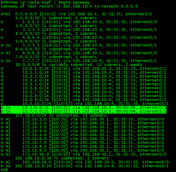

R2 and R3 which are also ABRs for area 30 will advertise the summary routes to R1 and finally R1 will redistribute the summary to R6 in the EIGRP domain as shown next:

Now that we saw the inter-area summarization let’s summarize the external routes redistributed from the EIGRP domain. For this purpose let’s summarize the 172.16.0.0/24 loopback addresses of R6 into a full /16 range.
In R1 we will find these routes as Type-7 LSA in the link state database because R1 is part of an NSSA area:

Now, let’s recall a bit here. Type-7 LSAs are not allowed beyond the NSSA area. The ABRs translate Type-7 into Type-5 LSAs. In our example, there are two ABRs. One of them will be elected translator.

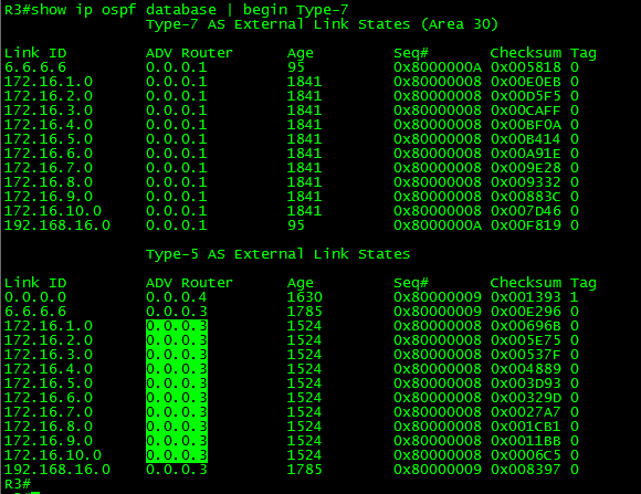
As seen in the above output, R3 was elected as “Translator”, and then the external routes were propagated to the OSPF domain as Type-5 LSA. Now, let’s summarize the routes and take a look at the results.
As mentioned before, external summarization must be done in the ASBR. Thus, the configuration goes into R1 which is the ASBR connecting OSPF and EIGRP.
!
router ospf 1
summary-address 172.16.0.0 255.255.0.0
!
Now, let’s take a look at the results in R2 and R3:

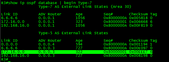
As expected, the external summarization works the same way as in inter-area summarization. The link-state database was reduced significantly as shown in R4.

To finish this long post I would like to suppress the discard route, just as a way to demonstrate that it can be done. However, I would not do it under normal circumstances.
First, let’s take a look at the discard route status:

Let’s suppress the discard route it in R1:
!
router ospf 1
no discard-route
!
Now let’s take a look at the discard route status:

As can be seen in the above output, after the configuration was done the discard route was suppressed from the routing table.
It is time to close this post. Thank you for visiting.


 WARNING.!