By design, OSPF implementations in Cisco devices refresh their LSAs every 30 minutes by default. If the LSA reaches its max age (3600 seconds), it will be discarded. If a router receives a new OSPF LSA, it will flood it over all interfaces belonging to the same area, except through the interface from where the LSA was received.
There are some topologies in which this behavior may result in unnecessary waste of bandwidth or network instability due excessive link use and CPU processing.
OSPF provides two different techniques that can be used to solve issues like the one described above:
OSPF database-filter:
With OSPF database-filter is possible the blocking of LSA flooding in the outbound direction. To configure this feature use the command ip ospf database-filter all out to the interface that connects to the area to be filtered. This command can also be used to block LSA flooding to specific neighbors in point-to-multipoint networks. This is achieved by using the OSPF process command neighbor {ip-address} database-filter all out, where the ip address is the one assigned to the interface connecting to the area, not be confused with the neighbor’s router-id.
OSPF flood-reduction:
With OSPF flood-reduction, the unwanted flooding is achieved by setting the DoNotAge (DNA) bit in the LSAs, therefore, the LSAs do not have to be refreshed every 30 minutes. To configure this feature use the ip ospf flood-reduction command to the desired interface.
When any of the above-described techniques is configured on an already established neighbor relationship, the adjacency will flap.
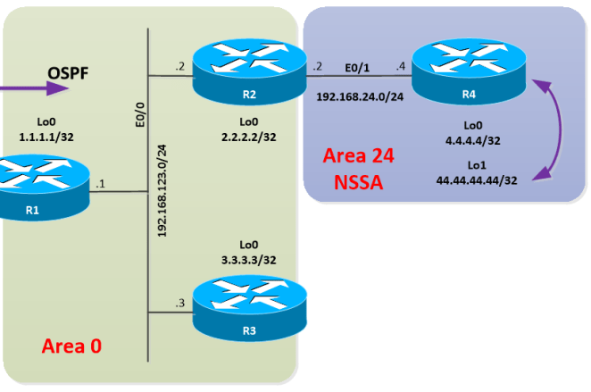
Let’s use the following topology for the examples:

Here you can download the diagram and configuration files: OSPF-Filtering – Part V
As can be seen in the diagram, the backbone area is connecting to Area 145 via a frame-relay cloud. The connectivity in the frame-relay cloud was configured as hub and spoke, where R1 is the hub.
Let’s start playing with filtering.
Goal 1:
Configure OSPF filtering on R1, in such way that LSAs towards area 145 are blocked. After the change was done verify connectivity to the network.
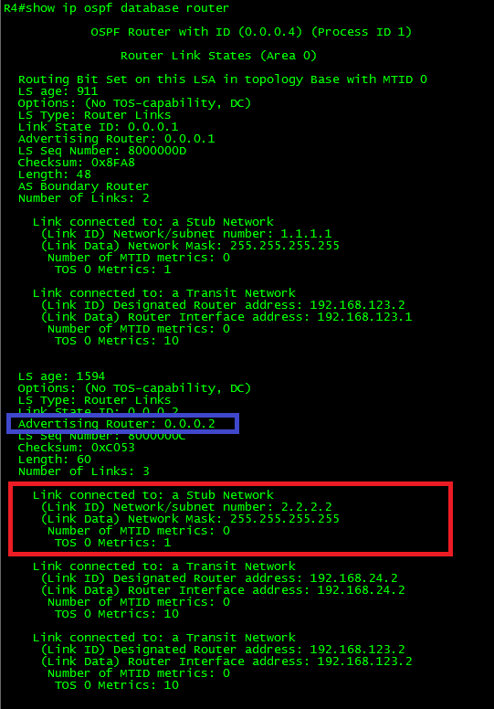
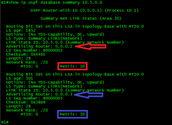
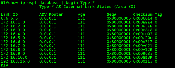
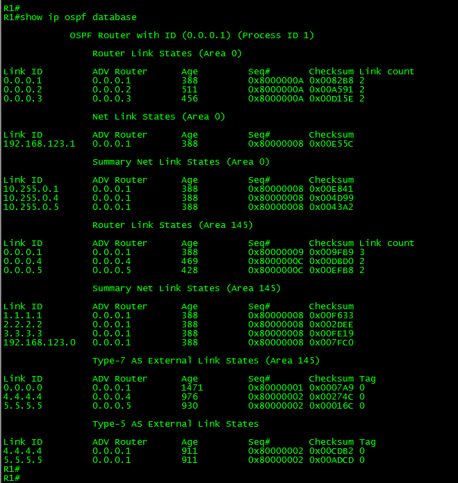
Ok, before applying the filter; let’s take a look at the LSDB to one of the spokes. (Remember, routers in the same area have identical copies of the LSDB, therefore, both spokes have an exact copy of the LSDB.)
As can be seen in the output, the current state of the database is stable, the LSDB contains Type-1 LSAs corresponding to R1, R4, and R5 respectively in Area 145, also is possible find Type-3 LSAs corresponding to the summary networks advertised by R1 (ABR); and finally, Type-7 LSAs corresponding to the redistributed loopbacks in R4 and R5 and the default route originated in R1.
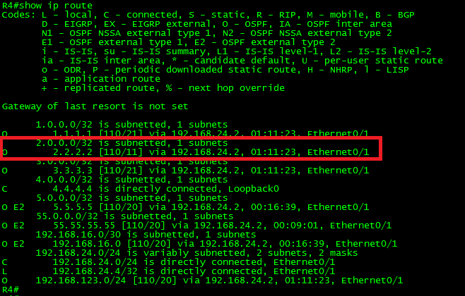
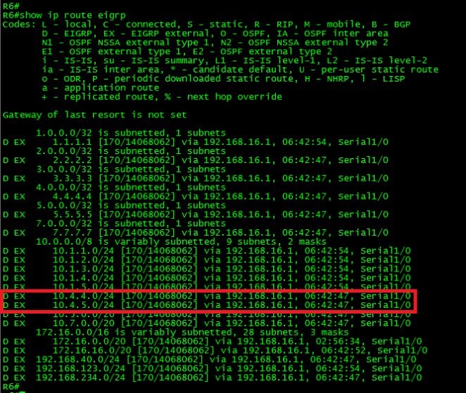
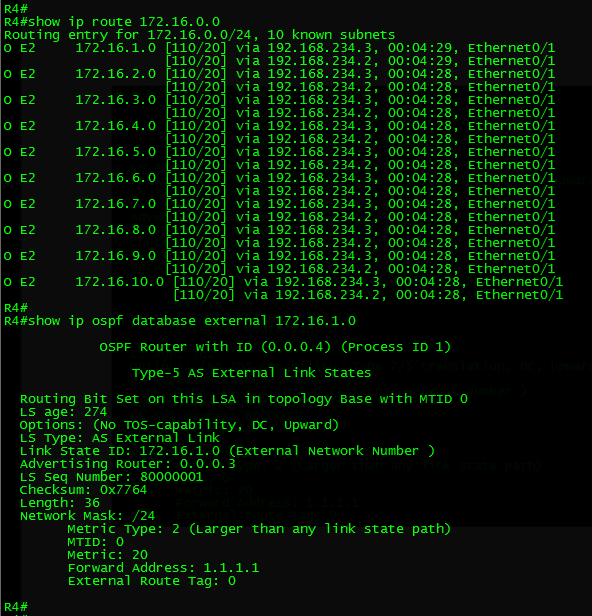
Next, let’s take a look to the routing table in R4:

As can be seen in the output, the routing table in R4 perfectly reflects the prefixes found in the LSDB: Intra-Area (O) routes corresponding to the Type-1 LSAs, Inter-Area Routes (O IA) corresponding to the Type-3 Summary LSAs and NSSA External (O N2) which corresponds to the Type-7 LSAs.
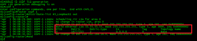
Now, let’s take a look from R1’s perspective.
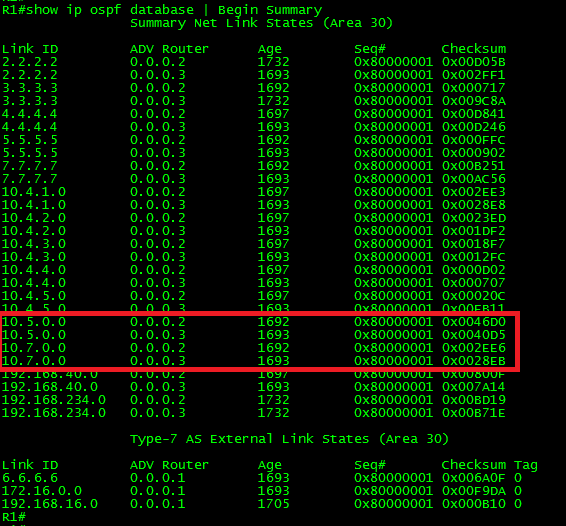
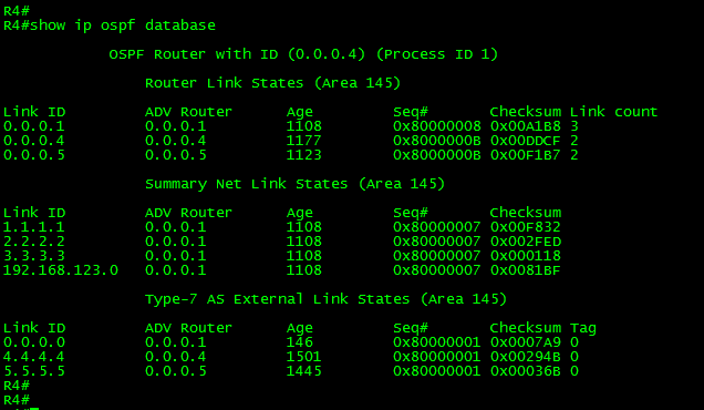
First, from the LSDB:
Ok, as can be seen in the above output, R1 has two views in its LSDB, one for each area respectively plus the Type-5 LSAs generated to advertise the redistributed routes coming from R4 and R5 in the NSSA.
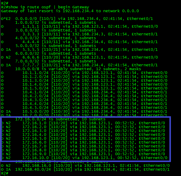
Now let’s take a look to the routing table in R1:

As can be seen in the output, R1 has OSPF intra-area routes for the loopbacks in R2 and R3 in area zero (0). Because R1 is the ABR connecting area 145, it also has NSSA External routes for the redistributed routes from R4 and R5. From the perspective of R2 or R3 for example, these routes instead NSSA External (Type-7 LSA) would be OSPF External (Type-5 LSAs). It is the same case for the intra-area routes corresponding to the serial1/0 interfaces of R4 and R5; they were advertised as Type-1 LSAs because R1 has the Serial1/0 interface participating in the NSSA area, thus, the routes were advertised via Type-1 LSA. From the perspective of R2 or R3, these routes instead intra-area would be OSPF summary (Type-3 LSAs) routes.
Ok, now that we have verified the LSDB status, let’s apply the filter:
In R1:
!
interface Serial1/0
ip ospf database-filter all out
exit
!
Immediately after the command was entered in the interface, the adjacencies with R4 and R5 were torn down and then re-established as shown next:

What was the result of this configuration?
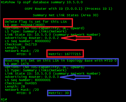
Let’s check the LSDB in R4:

As shown in the above output, apparently nothing happened. Well, this is not entirely true. With this command, you cannot see immediate results. As a matter of fact, now that the filter was applied and the LSAs refresh is no longer taking place, you have to wait until the LSAs age value reaches 3600 seconds (Max-Age value). Remember, Cisco OSPF-enabled routers refresh LSAs every 1800 seconds (1/2 hour), if an LSA reaches the max-age value then is flushed from the LSDB.
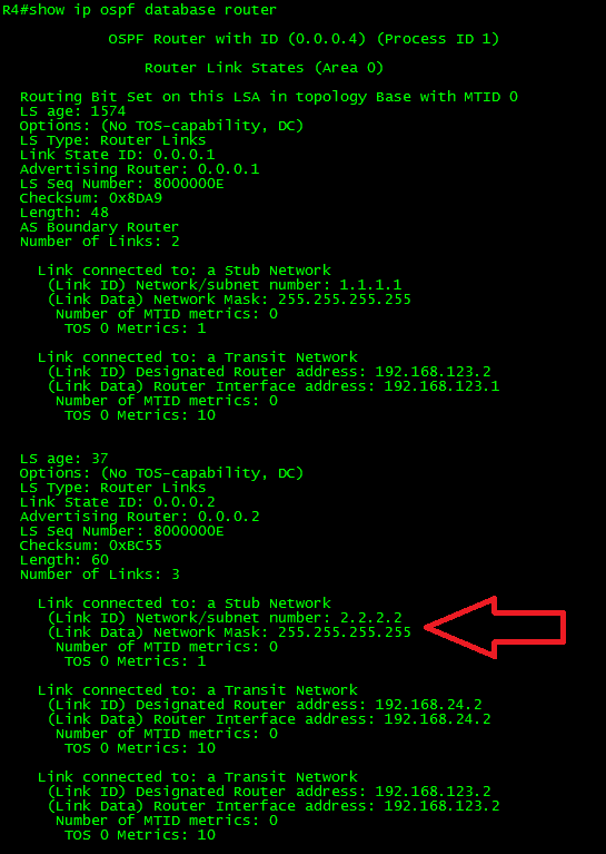
Let’s force the refresh to the LSDB by clearing the OSPF process in R4. (You probably don’t want to do this in production for obvious reasons.)
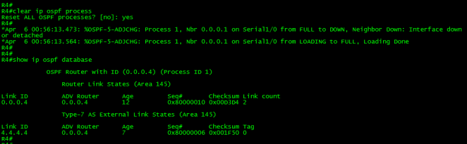
Ok, as can be seen in the above output, after we cleared the OSPF process in R4 the LSDB changed.
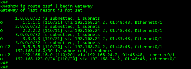
Let’s take a look now to the routing table in R4:
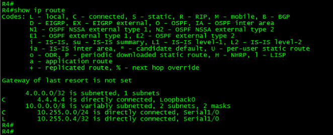
As can be seen in the above output, the routing table of R4 doesn’t have a single route learned via OSPF.
What happened here was that R1 is now filtering LSA updates to the routers in area 145; therefore, the LSDBs in R4 and R5 have flushed all LSAs with the max-age set.
However, the adjacency with R1 is still up; R4 continues sending hello packets and its LSAs to R1. This means that the routes for destinations advertised from the routers in area 145 will be present in R1 as shown in the next output.

Now, have you noticed a problem with this? No?
Well, after R4 and R5 cleared its LSDBs, the OSPF routes advertised by R1 have gone. Even the default route was cleared. The reason for this is that R1 was originating the default route via OSPF as a Type-7 LSA. So, although R1 knows the routes for networks advertised by R4 and R5, they are unreachable from R1 and any other routers in the OSPF domain.
The solution for this problem is very simple, just adding a default route on the spokes will solve the problem.
In R4 and R5:
!
config t
ip route 0.0.0.0 0.0.0.0 10.255.0.1
exit
!

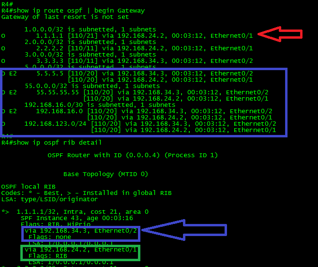
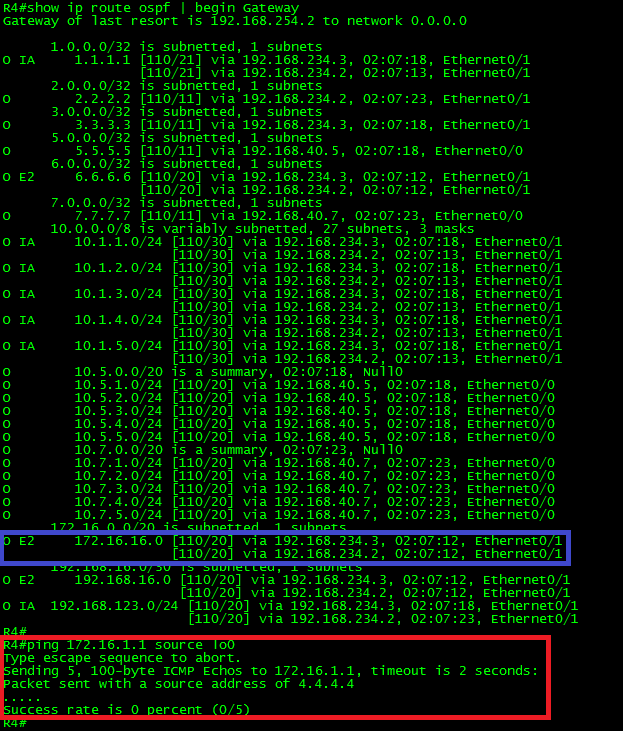
For brevity, I’m just showing the test from R4. With this, we can say that Goal 1 was achieved.
What could we have done if the goal instead of requesting the filtering of the entire area 145 would have required applying filtering only to R4?
Because the network type used in the configuration is point-to-multipoint, it could be possible use the variation of the command attached to the neighbor. Something like this:
In R1:
!
interface Serial1/0
no ip ospf database-filter all out
exit
!
router ospf 1
neighbor 10.255.0.4 database-filter all out
exit
!
Please note, in the above configuration, I have removed the filtering to the area. Instead, I applied the command into the OSPF process with the neighbor command. The result of this configuration will be the LSA database filtering taking place only in R4.
Let’s try the same scenario but with flood reduction:
Goal 2:
Configure OSPF filtering on R1, in such way that LSAs towards area 145 are reduced to the minimum. After the change was done verify connectivity to the network.
Let’s start by clearing the changes in R1, R4 and R5:
In R1:
!
interface Serial1/0
no ip ospf database-filter all out
exit
!
! If you tested the configuration applied with the neighbor command,
! please also proceed to remove it:
!
router ospf 1
no neighbor 10.255.0.4 database-filter all out
exit
!
In R4 and R5:
!
config t
no ip route 0.0.0.0 0.0.0.0 10.255.0.1
exit
!
Let’s take a look to the routing table and LSDB in R5:

As can be seen, R5 has full network visibility. The LSDB in R5 has Type-1 LSAs from the routers within the area 145, Type-3 LSAs from the links advertised in area zero and Type-7 LSAs corresponding to the default route and the redistributed routes from R4 and R5.
Let’s apply flood-reduction as requested.
In R1:
!
interface Serial1/0
ip ospf flood-reduction
exit
!
Yes, as simple as that.
The first thing you may note is that after applying the filter, the adjacency was torn down and then re-established, the same way happened with the database-filter command.
Another similarity is that you also have to wait until the LSAs age reaches 3600 seconds (Max-Age value) for the change takes effect. The only one that has actually changed was the Type-1 LSA corresponding to R1 as shown next.

As can be seen in the above output, the router LSA (Type-1) corresponding to the neighbor R1 now has the DNA (DoNotAge) bit set.
Let’s clear the process in R2 to accelerate the LSA aging to all of them and let’s talk about this feature a little bit more.

As can be seen, now all non-self-generated LSAs have the DNA bit set. Therefore, the LSAs won’t be refreshed every 30 minutes as normally OSPF does. This doesn’t mean that changes in the topology won’t be received.
Let’s shut down the loopback interface in R2 to verify this statement:
In R2:
!
interface Loopback0
shutdown
exit
!

As can be seen in the above output of R5, the Type-3 LSA corresponding to the loopback0 interface in R2 immediately started to age until reached max-age. Afterward, it was flushed from the LSDB.
What if we re-enable it?
In R2:
!
interface Loopback0
no shutdown
exit
!

As can be seen in the output of R5, the LSA was advertised to the area 145 with the DNS bit set.
The final step would be, just check the routing table of R5 and test reachability:

As shown in the above output, the routing table has full visibility of the network.
Before closing this post, let me mention another OSPF feature similar to OSPF flood-reduction: OSPF Demand Circuit. This feature was introduced in Cisco IOS since version 11.2 and is described in RFC 1793 (Old stuff.) and was created in response to the problem of OSPF updates being send over pay-per-packet links such dial-up or ISDN. The main difference between flood-reduction and OSPF demand circuit is that demand circuit is negotiated between the endpoints and also filters hello packets in addition to the LSA refresh while leaving the adjacency up.
This means that the adjacency will remain up even after the layer two of the circuit goes down.
To configure OSPF demand circuit, use the command ip ospf demand-circuit to the interface that connects to the far-end router.
It is time to close this long post. In the next one, we will discuss OSPF Default Routing and its variants.
Thank you for visiting.