In a multi-area OSPF network, all areas must be connected to the backbone area Zero (0), otherwise, no inter-area communications are possible.
Virtual-Links are OSPF tunnel interfaces used to solve situations where is necessary connecting a nonzero area to the backbone using another nonzero area as transit.
Let’s use the following example to illustrate the problem:

Relevant Configuration:
R1:
!
interface Loopback0
ip address 1.1.1.1 255.255.255.255
ip ospf 1 area 0
!
interface Ethernet0/0
ip address 192.168.12.1 255.255.255.0
ip ospf 1 area 0
!
router ospf 1
router-id 0.0.0.1
!
R2:
!
interface Loopback0
ip address 2.2.2.2 255.255.255.255
ip ospf 1 area 0
!
interface Ethernet0/0
ip address 192.168.12.2 255.255.255.0
ip ospf 1 area 0
!
interface Serial1/0
ip address 192.168.24.2 255.255.255.0
ip ospf 1 area 24
!
router ospf 1
router-id 0.0.0.2
!
R3:
!
interface Loopback0
ip address 3.3.3.3 255.255.255.255
ip ospf 1 area 0
!
interface Ethernet0/0
ip address 192.168.12.3 255.255.255.0
ip ospf 1 area 0
!
router ospf 1
router-id 0.0.0.3
!
R4:
!
interface Loopback0
ip address 4.4.4.4 255.255.255.255
ip ospf 1 area 45
!
interface Ethernet0/0
ip address 192.168.45.4 255.255.255.0
ip ospf 1 area 45
!
interface Serial1/0
ip address 192.168.24.4 255.255.255.0
ip ospf 1 area 24
!
router ospf 1
router-id 0.0.0.4
!
R5:
!
interface Loopback0
ip address 5.5.5.5 255.255.255.255
ip ospf 1 area 24
!
interface Ethernet0/0
ip address 192.168.45.5 255.255.255.0
ip ospf 1 area 45
!
router ospf 1
router-id 0.0.0.5
!
As can be seen from the diagram, R2 and R4 have interfaces in multiple areas. R2 has an interface in Area 0 (backbone) and another interface in Area 24. R4 has an interface in Area 24 and another interface in area 45.
You might think that R2 and R4 are ABRs. However in Cisco deployments, for a router becomes ABR requires that at least one interface is connected to area 0 (backbone).
Now let’s take a look at the routing tables of R1 and R5 respectively.


As can be seen in the above outputs, R1 has OSPF routes of the loopback interfaces of R2, R3, and R4 and also has the route of the segment 192.168.24.0/24 which connects R2 and R4. However, the route of the segment 192.168.45.0/24 and the loopback of R5 are missing. In R5 only the connected routes are present.
Now let’s question R1 and R5 about their known ABRs.


According to the above outputs, R1 identifies R2 as the only ABR in OSPF. R5 can’t identify any.
Remember, when a Router turns into an ABR what it does is set the “b” bit into its Type-1 LSA, then generates and flood Type-3 LSAS. The flooding scope of Type-3 LSA is a single area.
So, let’s take a look to R2 and R4 Type-1 LSAs and see if the b-bit is set. We know R2 has it. R1 already identifies R1 as ABR, but I want to show you the difference between them.


As expected, R2 has the “b” bit set and is claiming to be and ABR while R4 is not. This is the reason why the routes are not been propagated. In order that R4 become an ABR, it is necessary that one of its interfaces to be connected to the backbone area.
There are many ways to solve this problem. For example we can try renumbering the Area 45 and make a single area 24. Or we can just connect an interface between R2 and R5 as part of area 45. But what if none of these solutions are possible? What if the devices don’t have free interfaces or they are placed too far from each other? What if renumbering the area is not allowed?
Well, in this case we can use OSPF virtual-links or GRE tunnels. In my humble opinion, it is better to use Virtual-Links instead of GRE. To start, GRE is process-switched. GRE also adds encapsulation overhead. GRE encapsulates data traffic and routing traffic unlike Virtual-links, where only the routing updates are tunneled. The only advantage of GRE over Virtual-Links is that supports tunnels through stub areas. So let’s try using virtual-links and in a following post I will explain how to use GRE.
Let’s take a look to the requirements to configure the virtual-link:
- The transit area cannot be a stub area.
- The transit area shouldn’t have filtering.
- The transit area must have full routing information.
Looking at the configuration files exposed before, note that Area 24 is a normal area and there is no filtering applied. The last thing we need to verify is the transit area routing information. If it has full routing information then using a virtual-link is possible. Let’s take a look to the routing table of R4 to verify this.

As can be seen in the above output, R4 which is the router connecting has full routing information. This means that Area 24 can be used as transit.
Let’s move on the configuration:
To configure the OSPF virtual-link, use the command area {transit-area-id} virtual-link {destination-router-id}. This command goes in the OSPF process definition both routers forming part of the transit area (R2 and R4).

R2:
!
router ospf 1
area 24 virtual-link 0.0.0.4
!
R4:
!
router ospf 1
area 24 virtual-link 0.0.0.2
!
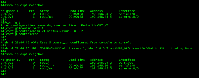
After the configuration was done, a new adjacency was formed via interface OSPF_VL0.
This “interface” is as a matter of fact is a multi-hop point-to-point unicast adjacency; it is in essence an extension of Area 0 across the transit area.
Let’s take a look to the virtual link using the command show ip ospf virtual-links.

As can be seen in the above output, the virtual-link is a demand circuit. This is a legacy concept coming from back on the day where dialup or ISDN circuits were in use. Back then the customers pay the link depending on the connect time or usage. Also note the Hello is suppressed and the DoNotAge LSA is allowed. This means that once the virtual link is up, no hellos are exchanged and the normal LSU refresh (every 30 minutes) won’t take place. These things must be taken into account when doing troubleshooting. In some cases is necessary clearing the ospf process for the changes take place.
Let’s take a look to the link-state Database.

The above output show the DNA (DoNotAge) bit set in some LSAs. Also note that R4 now show Type-1 LSAs from Area 0.
Let’s take a look of the self-originated Type-1 LSA of R4.

As can be seen on the above output, now R4 is setting the “b” bit to its Type-1 LSAs. This means that R4 has turn into an ABR.
Finally let’s take a look to the routing table of R5:
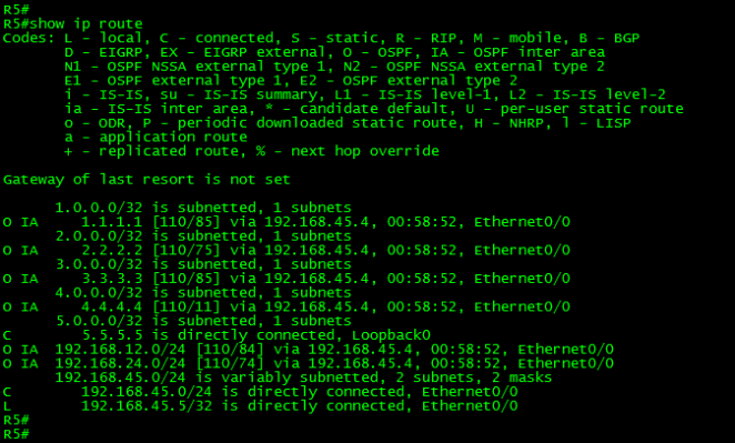
Now R5 has full reachability to the network via the transit area.
It is time to close this long post. Thank you for visiting.
