In a previous post, we learned how to configure OSPF within a single area. Now it is time to consider what would happen if this single area grows to let’s say, hundreds of routers?
Well, with such large number of routers and segments; the network changes are inevitable. Having this in mind, we can anticipate some problems like frequent calculations of the shortest path first (SPF) algorithm, large link-state database and of course, a large routing table. In order to avoid these issues, OSPF allows large areas can be separated into smaller ones. This is also known as hierarchical routing.
Before go deep into this topic we have to recall the different OSPF router types:
- Internal Router – Routers that have all interfaces in the same area.
- Backbone Router – Routers where at least one OSPF interface must belong to area 0 (backbone area).
- Area Border Router (ABR) – In Cisco IOS are the Routers that have at least one OSPF interface connected to Area 0 and at least one OSPF interface belong to a non-backbone area. This may not be the case for different platforms where the only requirement is having the interfaces in different areas regardless if they are connected to the backbone area or not. IPEXPERT’s blog has an interesting post about this here.
- Autonomous System Boundary Router (ASBR) – Routers injecting routes (Redistribution) from another routing protocol.
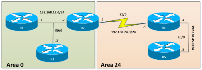
Let’s take a look at the following example:
Relevant Configuration:
R1:
!
interface Loopback0
ip address 1.1.1.1 255.255.255.255
ip ospf 1 area 0
!
interface Ethernet0/0
ip address 192.168.12.1 255.255.255.0
ip ospf 1 area 0
!
router ospf 1
router-id 0.0.0.1
!
R2:
!
interface Loopback0
ip address 2.2.2.2 255.255.255.255
ip ospf 1 area 0
!
interface Ethernet0/0
ip address 192.168.12.2 255.255.255.0
ip ospf 1 area 0
!
interface Serial1/0
ip address 192.168.24.2 255.255.255.0
ip ospf 1 area 24
!
router ospf 1
router-id 0.0.0.2
!
R3:
!
interface Loopback0
ip address 3.3.3.3 255.255.255.255
ip ospf 1 area 0
!
interface Ethernet0/0
ip address 192.168.12.3 255.255.255.0
ip ospf 1 area 0
!
router ospf 1
router-id 0.0.0.3
!
R4:
!
interface Loopback0
ip address 4.4.4.4 255.255.255.255
ip ospf 1 area 24
!
interface Ethernet0/0
ip address 192.168.45.4 255.255.255.0
ip ospf 1 area 24
!
interface Serial1/0
ip address 192.168.24.4 255.255.255.0
ip ospf 1 area 24
!
router ospf 1
router-id 0.0.0.4
!
R5:
!
interface Loopback0
ip address 5.5.5.5 255.255.255.255
ip ospf 1 area 24
!
interface Ethernet0/0
ip address 192.168.45.5 255.255.255.0
ip ospf 1 area 24
!
router ospf 1
router-id 0.0.0.5
!
Area Border Router
As mentioned earlier, ABR’s are used to connect non-backbone areas to Area 0. ABRs take the information contained in Type-1 and Type-2 and summarize it into Area 0. In the above example, R1, R2, and R3 are backbone routers. R2 is also acting as ABR between Area 0 and Area 24 respectively. R4 and R5 are internal routers of Area 24. R2 advertise itself as ABR by setting the “B” bit in its type 1 LSA.
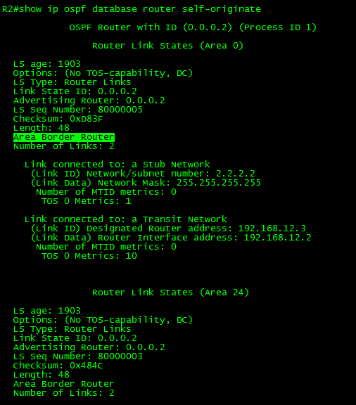
The above output displays the self-originated Type-1 (Router) LSA with the “B” bit set. This is the ABR in the current topology. Another way to identify ABRs is using the command show ip ospf border-routers.

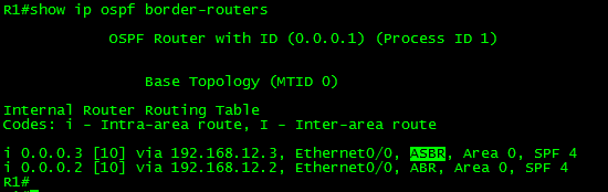
The above output displays the list of known ABRs from the perspective of R1.
Also, we have to keep in mind that an ABR keeps multiple copies of the link-state database, one for each area to which that router is connected. ABRs create and flood Type-3 (Summary) LSAs within areas; it will generate more than one summary LSA if the address cannot be properly aggregated by a single prefix (i.e. Host Routes or loopbacks).

As can be seen in the above output, R2 (ABR) has 2 copies of the link-state database. The Type-3 Summary LSA information of Area 0 details 2 networks (192.168.24.0/24 and 192.168.45.0) and 2 host routes (4.4.4.4 and 5.5.5.5) belonging to the loopbacks of R4 and R5 while the Summary LSA of Area 24 details a single network (192.168.12.0/24) and 3 host routes (1.1.1.1, 2.2.2.2 and 3.3.3.3) belonging to the loopbacks of R1, R2 and R3 respectively. In other words, the ABR is actually hiding the topology information within areas.
Now, let’s take a look to the routing table of R1 and see how to reach R5’s loopback:

As can be seen in the above output, the routing table shows the routes belonging to area 24 as “O IA” meaning inter-area routing. The intra-area routes of Area 0 are shown as “O”. Another important thing to denote is the actual route to the loopback 0 of R5. As you can see, the metric to reach 5.5.5.5 is 85 from R5. This is because the metric is additive in this case. It is the sum of the cost to reach the loopback of R5 from R1. (R1—10—R2—64—R4—10—R5—1—Lo0 = 85). The route describes the next hop: “192.168.12.2, from 0.0.0.2”, which is the next-hop IP address and the Router-ID of R2. R2 is the advertising the route on behalf of R5, not an IP address.
Now let’s take a look at R2’s information for the same route.

Note the difference between the above output and the previous one. Here we can see the route to 5.5.5.5 shown as “O” intra-area. This is because R2 has the interface Serial1/0 in area 24; this makes the route internal for it. From R2, the metric has also decreased to 75. The route describes the next hop: “192.168.24.4, from 0.0.0.5”, which is the next-hop IP address of R4 and the Router-ID of R5 which is advertising router.
Let’s take a look at R4’s information for the same route.

As can be seen in the above output, the routing table shows the routes belonging to area 0 as “O IA” meaning inter-area routing. The route to 5.5.5.5 is an intra-area route OSPF. As expected, the metric has decreased to 11. The route describes the next hop: “192.168.45.5, from 0.0.0.5”, which is the next-hop IP and the Router-ID of R5.
Finally in R5, ospf advertise the loopback 0 with Cost of 1.

ABRs also create and flood Type-4 (ASBR Summary) LSAs when an ASBR is present. This LSA is used to let other areas know where the ASBR is.
Autonomous System Boundary Router
ASBRs are routers injecting routes from another routing protocol or autonomous system. The injection is done via Redistribution. ABRs generate and flood Type-5 LSAs.
To inject routes into the OSPF domain, use the redistribute {connected|static|protocol}{metric <0-16777214>} {metric-type <1|2>} {subnets} {route-map} {tag <0-4294967295>} OSPF process command.
- The {connected|static|protocol} statement is self-explanatory. It defines the source of the routes to be redistributed.
- The {metric} keyword set the Cost of the route to be advertised. If the metric is not specified, OSPF will use a default value of 20 when redistributing routes from all IGPs. When redistributing from BGP, the metric will be 1 by default.
- The {metric-type} keyword forces the routes to be advertised as External Type 1 or Type 2. By default, Type 2 is used. For more information about the route Types and LSA Types, please see the post OSPF LSA Flooding Scope.
- The {subnets} keyword is required when redistributing subnetted networks. Without this keyword, only major networks will be redistributed.
- The {route-map} keyword is an enhancement to the redistribution process. It allows using different policies for redistribution.
- The {tag} keyword as its name implies, set a numeric tag value to the routes to be redistributed. This is widely used to control redistribution between protocols.
More on {route-maps} and {tags} in future posts.
For example, let’s use the same topology but we will configure R3 as ASBR:

In R3 we will make the following changes:
First, we will add two loopback interfaces and configure RIP:
!
interface Loopback10
ip address 10.10.10.10 255.255.255.0
!
interface Loopback20
ip address 20.20.20.20 255.255.255.0
!
router rip
version 2
network 10.0.0.0
network 20.0.0.0
no auto-summary
!
Finally, we will redistribute RIP into OSPF:
!
router ospf 1
redistribute rip metric 200 subnets
!
After redistribution was configured, R3 advertise itself as ASBR by setting the “E” bit in its type 1 LSA.

The above output displays the self-originated Type-1 (Router) LSA with the “E” bit set. This is the ASBR in the current topology. Another way to identify ASBRs is using the command show ip ospf border-routers.
Now let’s take a look at the link-state Database of R1 and its routing table.
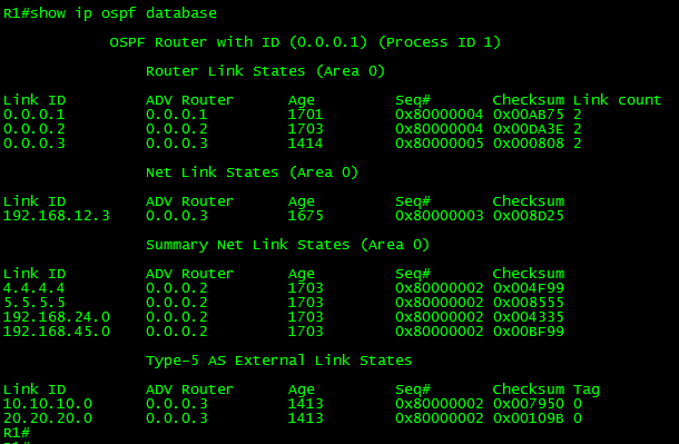

As can be seen in the above output, R1 only has Type-1, Type2, Type-3 and Type-5 LSAs in their databases. R1 and R3 have identical link-state Databases. The routes to reach the RIP routes are “O E2” OSPF external routes Type 2.
Now, R2 is an ABR and contains identical database information as R1 and R3 for area 0. R2 also has a database for area 24.
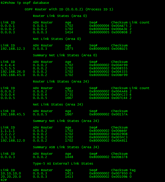
The database of R2 for Area 24 contains Type-1, Type-2, Type-3, Type-4 and Type-5 LSAs. As mentioned before, Type-4 LSAs are used to inform other areas where the ASBR is located. It is used basically to provide reachability information for the ASBR.
R4 and R5 are internal routers of Area 24; they share the same database information. For brevity, let’s focus in R5.
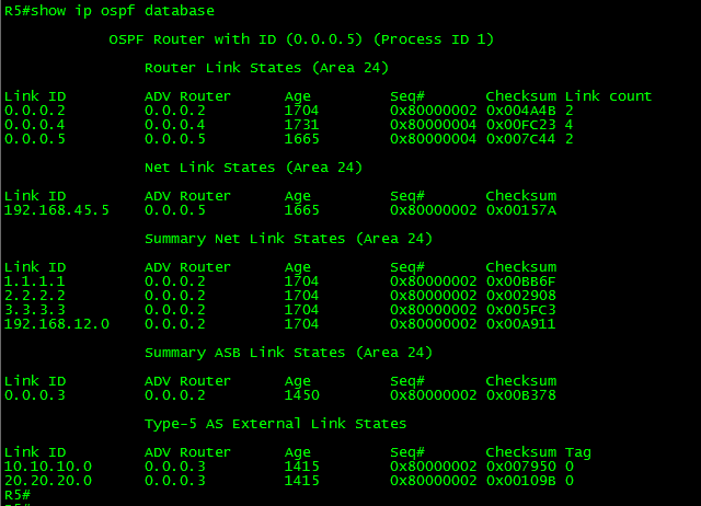

As expected, the link-state Database contains Type-1, Type-2, Type-3, Type-4 and Type-5 LSAs and the routing table show the routes as “O E2” OSPF External routes type 2.
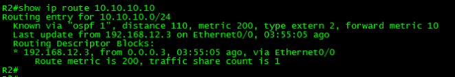
Finally, let’s try to reach the IP address 10.10.10.10 from R5.
Let’s get started looking for the route itself:
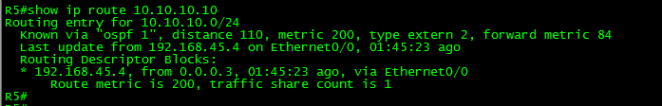
As you can see, the route is known by OSPF, the reported metric of the route is 200. We have defined this metric when redistributing the route. The route is External Type-2. This is the advertised cost from the ASBR to the external destination network. The forward metric is 84. This metric is the total cost to the ASBR from R5.
The route describes the next hop: “192.168.45.4, from 0.0.0.3”, which is the IP address of R4 and the Router-ID of the advertising router R3 (ASBR).
Now let’s check R4 and R2:
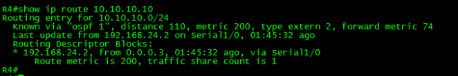
As can be seen in the above outputs, the only change is metric and the next-hop to reach the advertising router.
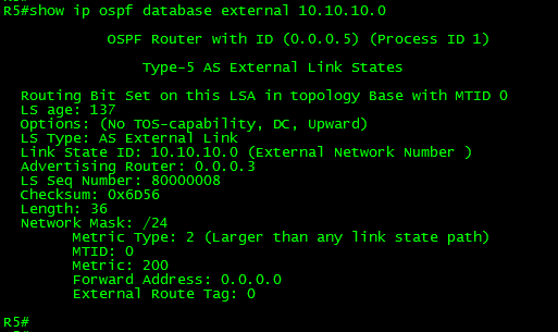
The advertising router remains the same because the forwarding address in the Type-5 LSA is set to 0.0.0.0 (null). This means that the route is reachable only via the advertising router.
It is time to close this long post. Thank you for visiting.
