In a previous post (OSPF Areas and Area Types), I have mentioned that Area 0 is the backbone Area. In a multi-area OSPF autonomous system, all areas must be connected to the backbone area Zero (0), otherwise, no inter-area communications are possible. Now, since Area 0 is the backbone, it must be a contiguous area.
In situations where is not possible to connect an area with the Backbone, OSPF Virtual links enter to play.
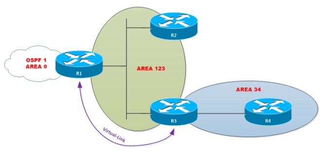
Let’s take a look to the following topology:

In this example, R1 has a link in Area 0 and other in Area 123. R1 is acting as ABR between area 0 and routers in area 123. Area 123 is configured as a normal area.
R2 has routes from Area 0 advertised from R1 (ABR) as Type-3 LSAs and also has routes from within the area 123 (Type-1 and 2 LSAs); however it does not have any route or paths to R4 networks.
R3 like R2 has routes from Area 0 advertised from R2 (ABR) as Type 3 LSA, also has routes from within the area 123 (Type-1 and 2 LSAs); also has routes within the area 34 (Type 1 and 2 LSAs). R3 does not have a link in Area 0; therefore, it is not an ABR (Which is a requirement to be an ABR). Then it cannot generate Type-3 LSAs nor advertise networks to and from R4.
Finally, R4 has routes of area 34 (if any) but has no route for networks in areas 0 or area 123.
To solve this problem Virtual-links and GRE tunnels can be used, however, there are some “disadvantages” using GRE over Virtual Links which worth mentioning:
- Encapsulation overhead.
- GRE is process-switched.
- GRE require more configurations.
- Routing LSAs and Data traffic are encapsulated in GRE.
Now GRE over Virtual-Links has a big advantage which worth to mention: With GRE the transit area can be of any Type, meaning that supports Stub Areas and its variants.
A Virtual Link is an OSPF tunnel, a multi-hop point-to-point unicast adjacency; it is, in essence, an extension of Area 0 across (transit area) another area. In the previous example, area 123 is the transit area between area 0 and area 34.
There are some restrictions that I have to mention:
- The transit area cannot be any type of stub area.
- The transit area shouldn’t have filtering configured.
- If a change is done on one side of the virtual link, the change must be replicated on the other end. For example, adding authentication or changing hello/dead timers must be done on both sides of the Virtual Link.
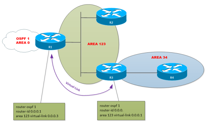
The virtual link must be defined between the ABR and the node connecting the discontiguous area (transit area). To create the virtual link use the command area x virtual-link [Router-ID].
Virtual links support additional features such authentication, hello/dead interval tuning and TTL-security. I will discuss this features in further posts.
Finally, there are some additional considerations to keep in mind when working with Virtual Links:
- When configured a P2P logical interface is created with state P2P and attached to Area 0.
- The default Timers of the Virtual Link interface is Hello 10 / Dead 40. However, the Hello packets in Virtual Links are suppressed by default.
- Virtual Links calculate its cost based on the cost of the Router connecting the discontiguous networks to the ABR.
- Virtual Links runs as a demand circuit. Misconfigurations in Virtual Links could not be detected until LSA flooding occurs. This is because LSAs originated by ABRs don’t age by default as occurs in LSAs originated for standard areas (30 mins by default).
