In a multi-area OSPF network, all areas must be connected to the backbone area Zero (0), otherwise, no inter-area communications are possible. Now, since Area 0 is the backbone, it must be a contiguous area.
Let’s start today’s post with these two statements. There are situations in which these rules are broken, whether caused by design problems, hardware issues or some broken link and so on.
Today there are two scenarios that would like to mention: Discontiguous backbone and discontiguous nonzero areas.
Interconnecting Discontiguous Backbone Area
Previously I wrote a post about how to solve situations where it is not possible to connect nonzero areas to the backbone using virtual links and the possibility of using GRE encapsulation for this purpose. Both solutions can be applied to connect the backbone area.
Let’s use the following example to illustrate the problem and possible solutions.

Let’s say we have the above network configured. The routers are configured as follows:
R1:
!
interface Loopback0
ip address 1.1.1.1 255.255.255.255
ip ospf 1 area 0
!
interface Ethernet0/0
ip address 192.168.13.1 255.255.255.0
ip ospf 1 area 0
!
interface Ethernet0/1
ip address 10.10.10.1 255.255.255.0
ip ospf 1 area 0
!
interface Serial1/0
ip address 192.168.12.1 255.255.255.0
ip ospf 1 area 0
!
router ospf 1
router-id 0.0.0.1
!
R2:
!
interface Loopback0
ip address 2.2.2.2 255.255.255.255
ip ospf 1 area 0
!
interface Ethernet0/0
ip address 192.168.24.2 255.255.255.0
ip ospf 1 area 0
!
interface Ethernet0/1
ip address 10.10.20.1 255.255.255.0
ip ospf 1 area 0
!
interface Serial1/0
ip address 192.168.12.2 255.255.255.0
ip ospf 1 area 0
!
router ospf 1
router-id 0.0.0.2
!
R3:
!
interface Loopback0
ip address 3.3.3.3 255.255.255.255
ip ospf 1 area 0
!
interface Loopback1
ip address 33.33.33.33 255.255.255.255
ip ospf 1 area 567
!
interface Ethernet0/0
ip address 192.168.13.3 255.255.255.0
ip ospf 1 area 0
!
interface Serial1/0
ip address 192.168.35.3 255.255.255.0
ip ospf 1 area 567
serial restart-delay 0
!
router ospf 1
router-id 0.0.0.3
!
R4:
!
interface Loopback0
ip address 4.4.4.4 255.255.255.255
ip ospf 1 area 0
!
interface Loopback1
ip address 44.44.44.44 255.255.255.255
ip ospf 1 area 567
!
interface Ethernet0/0
ip address 192.168.24.4 255.255.255.0
ip ospf 1 area 0
!
interface Serial1/0
ip address 192.168.46.4 255.255.255.0
ip ospf 1 area 567
!
router ospf 1
router-id 0.0.0.4
!
R5:
!
interface Loopback0
ip address 5.5.5.5 255.255.255.255
ip ospf 1 area 567
!
interface Ethernet0/0
ip address 192.168.100.5 255.255.255.0
ip ospf 1 area 567
!
interface Serial1/0
ip address 192.168.35.5 255.255.255.0
ip ospf 1 area 567
!
router ospf 1
router-id 0.0.0.5
!
R6:
!
interface Loopback0
ip address 6.6.6.6 255.255.255.255
ip ospf 1 area 567
!
interface Ethernet0/0
ip address 192.168.100.6 255.255.255.0
ip ospf 1 area 567
!
interface Serial1/0
ip address 192.168.46.6 255.255.255.0
ip ospf 1 area 567
serial restart-delay 0
!
router ospf 1
router-id 0.0.0.6
!
R7:
!
interface Loopback0
ip address 7.7.7.7 255.255.255.255
ip ospf 1 area 567
!
interface Ethernet0/0
ip address 192.168.100.7 255.255.255.0
ip ospf 1 area 567
!
router ospf 1
router-id 0.0.0.7
!
The network is stable, no problems so far, life is good.
Let’s take a look to the routing table of R1:
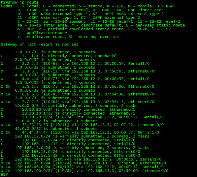
As can be seen in the above output, R1 has full visibility of the network.
Then after a while, Murphy’s Law occurs. “If anything can go wrong, it will.” A construction worker down the street accidentally breaks a fiber link. It turns out that the link between R1 and R2 runs through the broken fiber. What would be the effect on this? Yeah, you guessed right. A discontiguous OSPF Backbone.

Now, R1 has lost visibility of the networks advertised by R2 and vice versa. R2 can reach the networks in Area 567 but is unable to reach any network advertised by R1.
Let’s take a look at both routing tables.
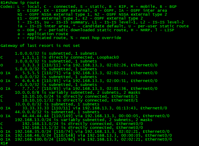

Have you noticed the difference? But what about the routing table of R7?
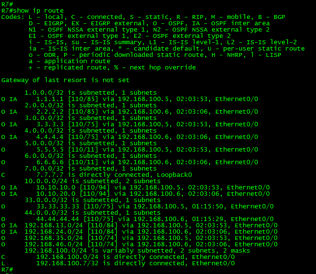
The routes to R1 and R2 are still reachable from there. This is because R3 and R4 acting as ABR’s are able to advertise these routes. Instead, R1 only see R3 as ABR and R2 only see R4 as ABR. Therefore, they only receive the routes from the routers in area 567.
Let me stop here to make a note on this:
This problem could be prevented by using Virtual-Links as a backup and for redundancy. Let me explain this a little bit more.
If we had a pre-configured virtual link between routers R3 and R4 an LSA will trigger SFP recalculation when the construction worker broke the link. Then the traffic between R1 and R2 will use Area 567 as transit to communicate. In other words, the backbone will remain continuous due redundant links. After the broken link was repaired, the SFP will be recalculated again and everything will be back to normal.

Let’s take a look at the required virtual-link configuration:
R3:
!
router ospf 1
area 567 virtual-link 0.0.0.4
!
R4:
!
router ospf 1
area 567 virtual-link 0.0.0.3
!
With this little change, the problem will be solved and we will provide redundancy at the same time.
Let’s temporarily apply the solution to the network and take a look to the routing table of R1:

As can be seen in the above output, R1 has full visibility again. But note the difference for the routes 2.2.2.2/32, 10.10.20.0/24 and 192.168.24.0/24. They are advertised as “O” or intra-area and reachable via the interface Ethernet0/0. Meaning routed through the transit area.
This seems to be the right solution in this case. However, among the immediate network update plans is change the area 567 to Stub. This means that virtual-link technology cannot be used. Virtual links are not supported in stub areas. So what can we do to solve the problem and provide redundancy at the same time? The solution could be creating a GRE tunnel and make it part of Area 0.
A GRE tunnel is a logical point-to-point interface which provides a way to encapsulate packets inside a transport protocol. I will not go in-depth with this technology today. However is necessary to mention some caveats using GRE. For example, GRE adds 24 bytes to a packet, this may cause fragmentation. Another important consideration is that it might introduce security issues because encapsulated packets may bypass access control lists (ACLs). In the earlier version of IOS, only process switching was supported. I’m mentioning this technology only as a feasible solution to the problem and the requirements on hand.
To configure the GRE tunnel between R3 and R4 we will need as a minimum a set of ip addresses to be assigned to the tunnels, source and destination ip addresses.
Let’s configure the tunnels with the following parameters:
R3:
!
interface Tunnel0
ip address 172.16.34.1 255.255.255.252
tunnel source Loopback1
tunnel destination 44.44.44.44
ip ospf 1 area 0
!
R4:
!
interface Tunnel0
ip address 172.16.34.2 255.255.255.252
tunnel source Loopback1
tunnel destination 33.33.33.33
ip ospf 1 area 0
!
The above configuration creates a GRE tunnel between R3 and R4. The network 172.16.34.0/30 was designated for this purpose. The source of each tunnel is the loopback1 on each router. Because OSPF routing is enabled on these interfaces, we are using the loopbacks itself to route through the area 567. The tunnel interfaces were also assigned to Area 0.
Let’s see what OSPF has to say about the interface:

As can be seen in the above output, the interface Tunnel0 in R3 looks like a regular interface. The network Type is Point-to-Point with a Cost of 1000. The interface also sends Hellos every 10 seconds, with a Dead timer of 40 seconds. It behaves as any other interface.
Let’s take a look again to the Routing table of R1 and R3.

As can be seen in the above output, R1 has full visibility again. But note the difference for the routes 2.2.2.2/32, 10.10.20.0/24 and 192.168.24.0/24. They are advertised as “O” or intra-area and reachable via the interface Tunnel0. The tunnel interface is routing the packets through the transit area 567.
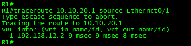
Finally, let’s trace a packet from 10.10.10.1 in R1 to 10.10.20.1 in R2:
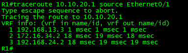
As can be seen in the above output, the trace works. The packet is routed to 192.168.13.3 (R3), then through the GRE tunnel (172.16.34.2 in R4) which seems only one hop away and finally to 192.168.24.2 (R2).
As soon the link was restored, the regular path was chosen:
Discontiguous Nonzero Areas
Having discontiguous non-zero areas is perfectly valid in OSPF. It is normal to assume that OSPF areas are intended to be unique and that must be contiguous. However we have to remember that the Area ID is used to build the SPT graph, in other words, is only used to create the neighbor relationship in OSPF. The area ID is not present in the routing updates.
When an ABR generate and flood LSAs to the Backbone AREA, it summarizes LSA information from a given area into Type-3 LSAs. The next hop in the Type-3 LSA is a given ABR, not an area ID. Routers in other areas are unaware of the source Area ID of the routes. Thus, it is possible having multiple discontiguous non-zero areas.
For example, let’s take a look to the Type-3 Summary LSA corresponding to the loopback of R7 in our last example from R1.

As can be seen in the above output, R1 is aware of the route 7.7.7.7/32 which was advertised to R1 from the ABRs (R3 and R4). R1 is unaware of the Area ID from where the route was learned.
It is time to close this post. Thank you for visiting.
